6
2.5 CHECK OIL LEVEL
Check the oil level only when the machine is not in operation and all
vacuum built up in the chamber has been vented. Be aware that the oil
may be very hot and avoid all contact.
Checking the Oil Level
* Check the oil level on a daily basis
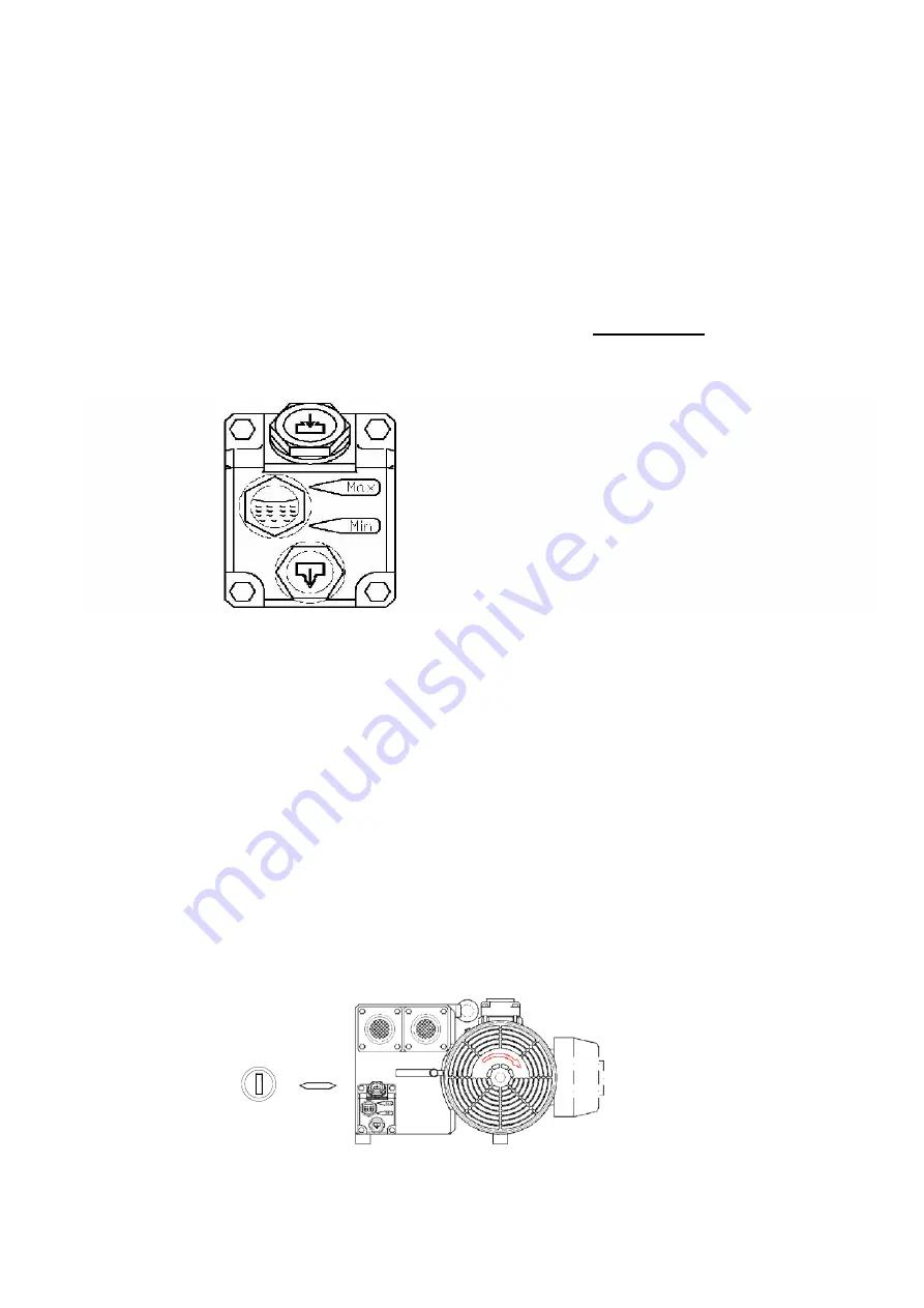
* When checking the oil level use the sight gauge shown in
figure 1 below
. The level
should be between the arrows indicating Minimum and Maximum. If the level is below the
minimum arrow add oil until the maximum arrow is reached.
Figure 1
2.6 POWER CONNECTION
When preparing to install the machine’s main power connection please refer to the electrical
information on the serial number plate located on the machine’s back panel. A certified
electrician should be employed to complete this connection.
2.7 VACUUM PUMP ROTATION
If your machine operates on 3 phase power it is important to check the rotation of the vacuum
pump. The pump should turn in the direction indicated in
Figure 2
below. If the pump turns
in the wrong direction it will make a sound that is obviously wrong. Turn off the power
immediately and change the position of two of the power wires and retest.
Figure 2
Main switch
Summary of Contents for Promax DC-640
Page 19: ...16 ...
Page 23: ...20 5 3 PNEUMATIC DIAGRAM ...
Page 24: ...21 5 4 ELECTRICAL DIAGRAM FB ...
Page 25: ...22 5 3 ELECTRICAL DIAGRAM TB ...
Page 27: ...6 1 BODY 24 DC64100000 Body Diagram ...
Page 29: ...6 2 WORKING BED BOTTOM 26 C C Working bed Bottom Diagram DC64200000 ...
Page 32: ...6 3 1 CUSHION BAR FB 29 Cushion Bar Diagram DC642FB000 ...
Page 34: ...6 3 2 CUSHION BAR FBG 31 DC642FBG00 Cushion Bar Diagram ...
Page 36: ...6 3 3 CUSHION BAR FBPK 33 DC642PK000 Cushion Bar Diagram ...
Page 38: ...6 3 4 CUSHION BAR FBPKG 35 DC642PKG00 Cushion Bar Diagram ...
Page 40: ...6 3 5 SEALING BAR BOTTOM FBTB 37 DC642TB000 Sealing Bar Bottom Diagram ...
Page 42: ...6 3 6 SEALING BAR BOTTOM FBTBG 39 DC642TBG00 Sealing Bar Bottom Diagram ...
Page 44: ...6 3 7 SEALING BAR BOTTOM FBTBPK 41 DC642TK000 Sealing Bar Bottom Diagram ...
Page 46: ...6 3 8 SEALING BAR BOTTOM FBTBPKG 43 DC642TKG00 Sealing Bar Bottom Diagram ...
Page 48: ...6 4 CHAMBER LID DIAGRAM 45 Chamber Lid Top Diagram DC80300000 ...
Page 50: ...6 5 1 SEALING BAR TOP FB 47 D64312A00 Sealing Bar Top Diagram ...
Page 53: ...6 5 2 SEALING BAR TOP PK 50 DC64350A00 Sealing Bar Top Diagram ...
Page 56: ...53 6 6 ELECTRICAL BOX FB 6 6 ELECTRICAL BOX TB ...


