USER MANUAL //
ELEVATOR PB-440
Review 01/19
43
05
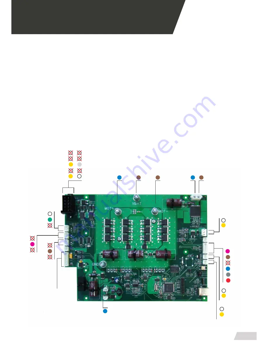
ELECTRICAL CIRCUIT DIAGRAM
05.1 Printed circuit board
Components
1.
Loading position (Control command)
14.
Tilt switch 2
2.
Micro-sensor (Loading handle)
15.
Tilt switch 1
3.
Zero position (Control command)
16.
Micro-switch for loading position (common)
4.
Micro-sensor (Unloading handle)
17.
Micro-switch for loading position
5.
Emergency stop
18.
Linear Actuator A1 (common)
6.
Subsequent signals (common)
19.
Linear Actuator A1
7.
Mains connection 12v +
20.
Motor
8.
Mains connection 12v -
21.
Motor (common)
9. Trendelemburg
declive
(Control command)
22.
LED (common)
10. Trendelemburg
proclive
(Control command)
23.
LED
11.
Upload platform (Control command)
24.
Buzzer (siren) (common)
12.
Download platform (Control command)
25.
Buzzer (siren)
13.
Common (Control command)
26.
Encoder
20
07
21
19
18
06
07
09
10
11
12
13
08
16
17
14
15
03
04
01
02
* Polarity inverts depending on the movement that it’s running.
22
25
23
24
26
Summary of Contents for PB-440
Page 1: ...USER GUIDE ELEVATOR PB 440 Review 01 19 ...
Page 2: ......
Page 4: ......
Page 10: ......
Page 13: ...USER MANUAL ELEVATOR PB 440 Review 01 19 13 03 OPERATING A 1 B C D E 2 3 4 5 ...
Page 14: ......
Page 16: ......
Page 42: ......
Page 49: ......


