-25-
1.
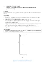
POSITION OF TOUCH PANEL
(Be sure to adjust the touch panel after reconnecting the touch
panel connector.)
STANDARD
The deviation between the liquid crystal display and touch panel should be within 1 mm when the touch panel is
pressed.
ADJUSTMENT
1.
While pressing the start/stop, reverse stitch and needle position buttons, turn on the power to display the
screen for the touch panel adjustment mode.
2.
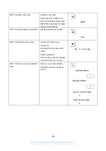
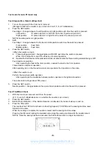
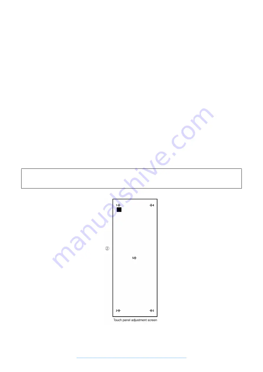
Touch the touch panel at the positions marked by crosses (+) in order from 1 to 5.
(When touching the touch panel, use the included touch pen. Never use a hard or sharp-pointed object.)
If the buzzer sounds once when cross number 5 is touched, the adjustment has been made correctly and
the square will be displayed in "Black".
If the buzzer sounds 4 times when cross number 5 is touched, an error has occurred and the square will be
displayed in "Red". In this case, touch the crosses on the touch panel again in order from 1 to 5.
Never press the thread cutter button during this time. (Doing so may cause a malfunction.)
3.
Turn the power off, then on again and check that the screen display and the touch panel positions are
aligned.
Adjustment Point
If the buzzer sounds more than twice while making adjustment (2), perform the procedure again from the
beginning since the position has not been correctly set.
www.promelectroavtomat.ru
Summary of Contents for M3000C
Page 4: ... 2 1 MECHANICAL CHART EMBROIDERY UNIT MECHANISM www promelectroavtomat ru ...
Page 6: ... 4 3 ELECTRONIC PARTS ARRANGEMENT CHART www promelectroavtomat ru ...
Page 13: ... 11 www promelectroavtomat ru ...
Page 17: ... 15 www promelectroavtomat ru ...
Page 19: ... 17 www promelectroavtomat ru ...
Page 25: ... 23 2 LEAD WIRE ARRANGEMENT www promelectroavtomat ru ...
Page 67: ...ULT2003D S G 3100D ULT2001N ULT2001C M3000N M3000C 11C03HF114200 www promelectroavtomat ru ...


