Maintenance manual Universal-1000
P R O M E T A L
42
In order to avoid an inclined setting-up of the tamper head (that can result in an unequal stone
height), supporting screws are placed before and behind the metal buffers. These screws
should be adjusted 1- 2 mm lower than rubber buffers in order to avoid transmission of
vibrations on to the tamper head bridge.
Also the two traction-discharge screws are installed on every side of the suspension which
prevents the metal buffers to be strained by tractive powers. With uncharged buffers backlash
of 1-2 mm should be maintained.
Setting the tamper head:
To set up tamper head stroke, please follow these instructions:
-
activate master switch on the control panel for the function:
tamper head up
SAFETY NOTE!
Before You start any inspection, maintenance or repair work,
insert first the tamper
head safety bolts!
-
insert four distance pieces into outer mould cavities, their height must be exactly
corresponding with the height of the intended products
-
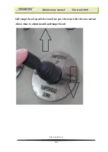
activate master switch on the control panel for the function:
tamper head down
(remove tamper head safety bolts first)
-
unscrew and
move to end down
position
tamper head stoppers
-
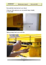
tight the both tamper head stoppers with all 4 screws
-
activate master switch on the control panel for the function:
tamper head up
-
remove the distance pieces from the mould
Now tamper head stroke is adjusted to wanted block height.
Maintenance on tamper head cylinders and bearings
The tamper head cylinders
must
be mainteined regulary!
Lubricate the pedestal bearings on every tamper head cylinders weekly (based on 1 shift,
every 50 hours).
Clean push rods on tamper head weekly (based on 1 shift, every 50 hours). Also check
condition of push rods.
Summary of Contents for UNIVERSAL 1000
Page 19: ...Maintenance manual Universal 1000 P R O M E T A L 19 ...
Page 25: ...Maintenance manual Universal 1000 P R O M E T A L 25 Hydraulic system ...
Page 26: ...Maintenance manual Universal 1000 P R O M E T A L 26 ...
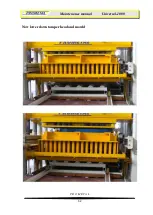
Page 52: ...Maintenance manual Universal 1000 P R O M E T A L 52 Now lower down tamper head and mould ...
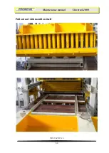
Page 53: ...Maintenance manual Universal 1000 P R O M E T A L 53 Pull out cart with mould on itself ...
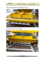
Page 58: ...Maintenance manual Universal 1000 P R O M E T A L 58 After adjustment is done ...
Page 65: ...Maintenance manual Universal 1000 P R O M E T A L 65 Vibrator table maintenance ...


