-14-
Mechanical Disassembly
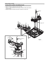
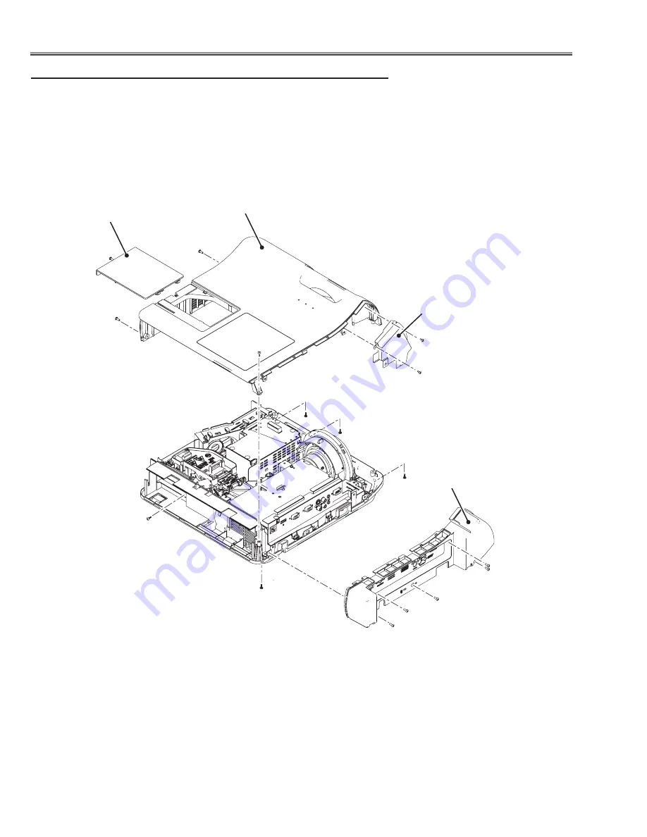
1. Remove 5 screws A(M3x8) to remove the AV Panel.
. Remove 3 screws B(T3x8), 1 screw C(T3x8), screws D(M3x8) and 1 screw E(T3x8)
and 1 screw F(T3x8) to remove the Cabinet Top assy.
3. Loosen 1 screw G and remove the Lamp Cover in the arrow direction.
4. Remove screws H(T3x8) to remove the Shield Plate.
Fig.2
x
AV Panel and Cabinet Top removal
A
A
A
A
B
B
C
B
d
d
e
F
G
H
H
Lamp Cover
Cabinet Top
Shield Plate
AV Panel
A
(Located on the center of
the cabinet bottom.)
Summary of Contents for PRM-30A
Page 58: ... 58 IC Block Diagrams L3E07111 Digital Gamma and Driver IC401 LC87F2G08A PIC Micom IC9885 ...
Page 59: ... 59 IC Block Diagrams MR4010 Power OSC IC631 NJW1156 Audio Selector IC5001 ...
Page 87: ...Key No Part No Description Key No Part No Description 87 Electrical Parts List KJ8 30A00 ...


