Pr
o
Minent
®
Page 9
Assembly and Installation
6.3
Electrical installation
WARNING
•
Installation must be carried out by a trained engineer!
•
Disconnect gamma/ L from mains power supply during installation!
•
Observe applicable national directives when installing the dosing pumps!
•
When connecting with parallel inductive power consumers a switch
contact must be fitted, e.g. relay or contactor!
Connection
to mains power supply
Connect the gamma/ L to the mains power supply using the mains lead
Parallel connection to
inductive power consumers
If the gamma/ L is connected to the mains in parallel with inductive power consumers
(e.g. solenoid valve, motor) they must be electrically isolated. This will avoid damage caused
by induction and voltage surges when switching off.
S
Fit individual contacts for the gamma/ L and supply power via auxiliary contactor or relay.
If this is not possible, then:
S
Connect a varistor in parallel (order number 710912) or an RC circuit, 0.22
m
F/220
W
(order number 710802).
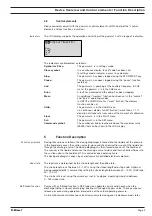
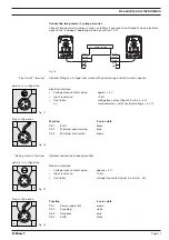
Power element
(in base of pump)
1
PE
L1
N
2
4
5
3
Fig. 07
1 Mains terminal
2 Relay circuit terminal
3 Fuse
4 Solenoid earth lead terminal
5 Solenoid terminal
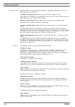
“External control”
terminal
The “external control” terminal is a five pin in-built terminal. It is compatible with the two and
four core cables used previously.
The “auxiliary frequency” function is only available with a five core cable.

