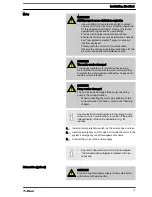
5.2 Testing Directly After the Pump has Started Up
With the pump running, check whether bubbles are rising in the oil
inspection window (336) above the bleed valve in the diaphragm
holder (300) - no foam!
Check whether liquids are escaping at any point.
Ensure that the back pressure on the discharge side is perma‐
nently above 1.5 bar (2.5 bar absolute).
Check whether the ratio of stroke length / metering frequency is
appropriate to the process.
Set the stroke length to prime to the maximum value on the scale.
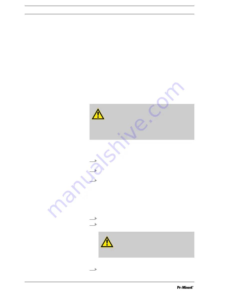
WARNING!
Risk of injury from the fan impeller
The fan impeller beneath motor's fan cowling can
cause severe injuries while it is turning.
– The pump must only be connected to the mains
voltage with the fan cowling closed.
With upright motors:
Check whether the drive motor is rotating correcting – refer to the
arrow on the motor flange.
1.
Unscrew the screw from the control opening on the motor
flange.
2.
Push a long thin piece of cardboard a little way into the
opening with the motor running.
3.
Remove the cardboard from the opening.
ð
The bend of the cardboard shows the direction of rota‐
tion.
With multiple pumps:
Check whether the drive shaft is rotating correctly - refer to the
arrow on the connecting flange between the drive units.
1.
Unscrew the drive unit cover when the motor is at a standstill.
2.
Carefully place a long thin piece of cardboard onto the end of
the shaft with the motor running.
WARNING!
Risk of injury
Never touch the end of the shaft with your fin‐
gers.
ð
The cardboard indicates the direction of rotation.
3.
When the motor is stopped: Screw the drive unit cover onto
the drive unit.
Checking the hydraulic oil flow
Checking for leaks
Setting the back pressure
Checking the stroke length / metering
rate
Setting the stroke length to the max‐
imum value on the scale
Checking the direction of rotation
Start Up and Operation
24


