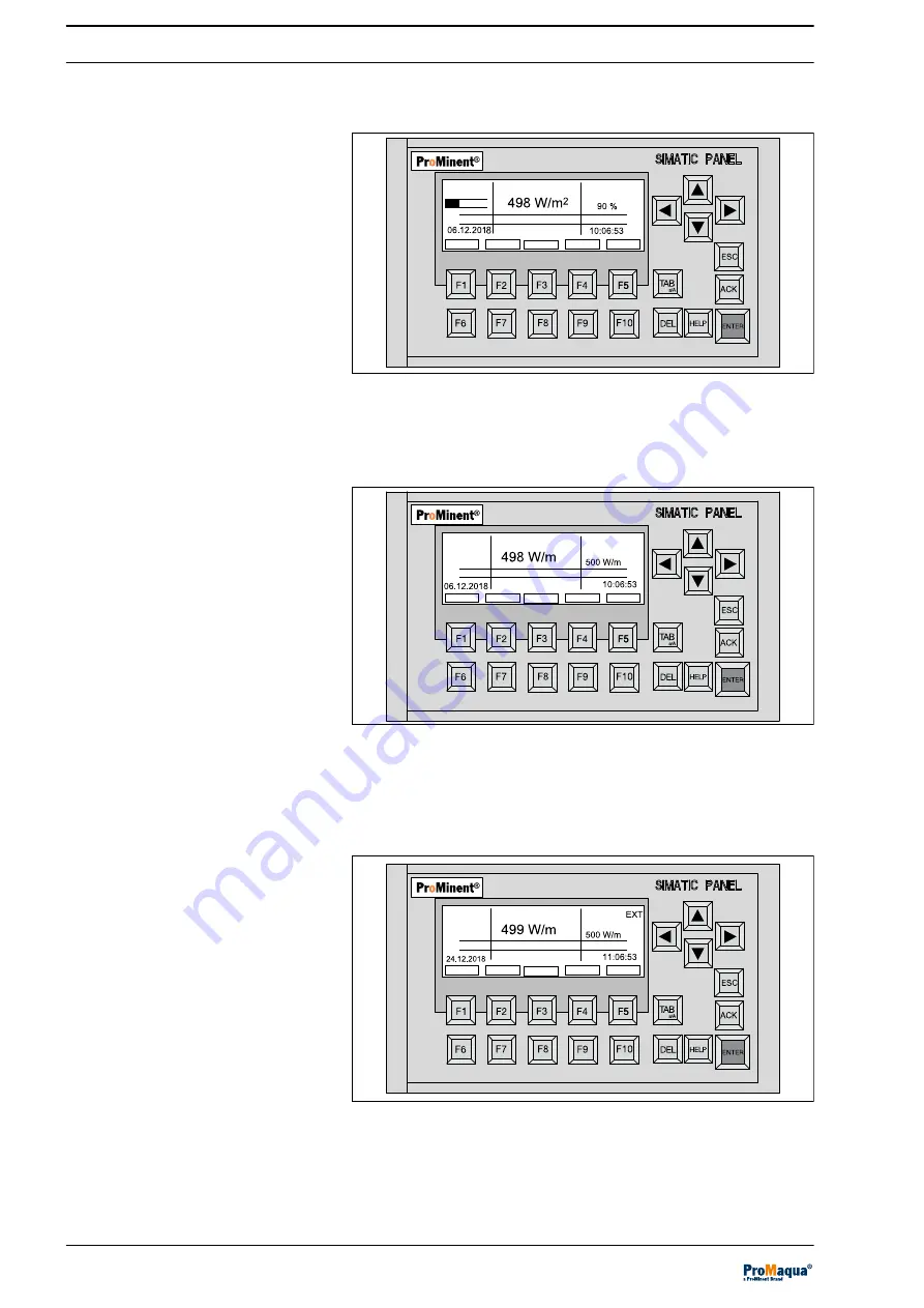
The display corresponds to the control as a % of the maximum
power of the UV lamps.
A1190
STOP
Fault
Menu
Wiper cycle
Control
INT
Time: 00:01
Lamp power 1x1979 W
Lamp ON
Wiper
Trend
UV intensity
Lamp power
Rinsing valve open
Fig. 7: [INT], constant electrical power
The display corresponds to the control in W/m
2
based on the UV
sensor signal.
A1515
STOP
Fault
Menu
2
Control
INT
Time: 00:01
Lamp power 1x979 W
Lamp ON
Wiper
Trend
UV intensity
2
UV intensity
Rinsing valve open
UV dose
600 J/m
2
Fig. 8: [INT] control, UV sensor signal in W/m² of the maximum UV
sensor signal
The display corresponds to the control in W/m
2
based on the UV
sensor signal.
A1611
STOP
Fault
Menu
2
Control
Time: 00:01
Lamp power 1x979 W
Lamp ON
Wiper
Trend
UV intensity
2
UV intensity
Rinsing valve open
UV dose
600 J/m
2
Fig. 9: [EXT] control, UV sensor signal
[INT] control, constant electrical power
of the UV lamp
[INT] control, UV sensor signal in
W/m²
[EXT] control, UV sensor signal
Control
22


