background image

Follow these steps to install the hard disks:

1.  Press the drive carrier release button. The handle springs open.

2. 

Grasp the handle and gently pull the empty drive carrier out of the 

enclosure.

Cautions

Swing open the drive carrier handle before you 

insert the drive carrier into the enclosure.

To avoid hand contact with an electrical hazard, 

remove only one drive carrier a time.

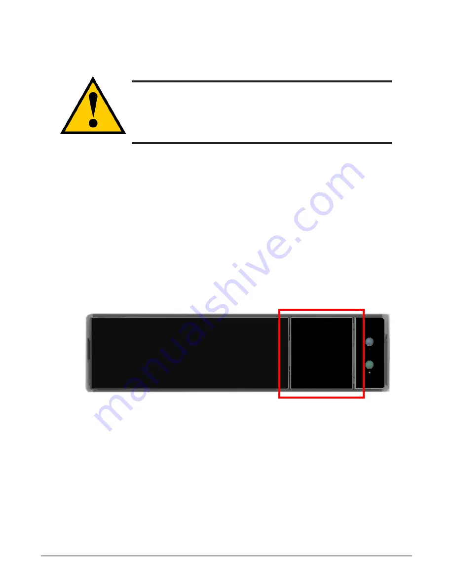
Disk carrier release button

Drive carrier front view

9

Vess A6120

Storage Server Appliance

Summary of Contents for Vess A6120

Page 1: ...Vess A6120 NVR Storage Appliance Quick Start Guide Version 1 0 2016 PROMISE Technology Inc All Rights Reserved ...

Page 2: ...gement Connection 11 Management Path on site keyboard and monitor 11 Management Path network connection 12 Task 5 Connecting the Power 12 Power On Vess A6120 system 12 Back Panel LEDs 13 Front Panel LEDs 14 Task 6 Access Operating System GUI 15 Log in to Windows 16 Task 7 Creating Logical Drives 17 Logging into WebPAM PROe 17 Choosing a Language 18 Creating Your Logical Drives 19 System Shutdown 2...

Page 3: ...26 Available PCI PMC Hardware Combinations 27 Product Registration 29 Register your Vess A Series 31 Open a web support case 33 Contacting Technical Support 35 Technical Support Services 35 iii Vess A6120 NVR Storage Appliance ...

Page 4: ...n how to connect the system to the surveillance network connect to additional network storage if needed how to install video management software how to administer manage and maintain the system as well as how best to scale the system to suit the requirements of your surveillance and data storage network This guide also includes information about Product Registration page 29 Contacting Technical Su...

Page 5: ... on system Task 6 Login to Windows Task 7 Login to WebPAM PROe Task 8 Create Logical Drives Task 1 Unpack Vess A6120 Packing List The Vess A6120 box contains the following items Vess A6120 Front bezel secure cover 1 5m 4 9 ft Power cord Screws for disk drives 20 pieces for 4 bays Sliding rail assembly for rack mounting Note The Product Manual and this Quick Start Guide in PDF format are found on t...

Page 6: ...n various LEDs USB ports and the tubular lock See Power On Vess A6120 system on page 12 and Front Panel LEDs on page 14 in this guide for more information Front panel overview No Description 1 4 x 3 5 Hot Swap HDD Trays HDD0 HDD3 2 2 x USB 2 0 Ports 3 Control Panel Buttons and LEDs 4 VGA Port HDD0 HDD1 HDD2 HDD3 1 2 3 4 Front Panel without bezel cover Front Panel with bezel cover 3 3 Vess A6120 St...

Page 7: ...PCIe hardware options The types of ports and connections available on the Vess A6120 include Two port 10G BASE T Two port 10G SFP Two port 1G BASE T Four port 1G BASE T SAS HBA SFF 8644 M 2 RAID card For a complete list of the available port options please see the Product Manual For a brief overview of PCIe and PMC hardware options see PCI PMC add on hardware on page 26 Vess A6120 rear view VGA po...

Page 8: ...nt Therefore consideration should be given to installing the equipment in an environment compatible with the maximum ambient temperature Tma specified by the manufacturer Reduced Air Flow Installation of the equipment in a rack should be such that the amount of air flow required for safe operation of the equipment is not compromised Mechanical Loading Mounting of the equipment in the rack should b...

Page 9: ...de 1 For both sliding rail assemblies release and detach the inner member from the slide 2 Attach the inner member of the sliding rail assembly to each side of the Vess A6120 Follow these steps to install the mounting rails in an equipment rack ...

Page 10: ...7 Vess A6120 Storage Server Appliance 3 Fix the outer member of the rail assembly to the rack frame 4 Carefully insert the Vess A6120 to complete the installation ...

Page 11: ... 3 5 inch hard disk drives For a list of supported physical drives download the latest compatibility list from the PROMISE support website Empty drive carrier side view Front Empty drive carrier top view Front Drive carrier hardware Promise Technology 8 Quick Installation Guide ...

Page 12: ... gently pull the empty drive carrier out of the enclosure Cautions Swing open the drive carrier handle before you insert the drive carrier into the enclosure To avoid hand contact with an electrical hazard remove only one drive carrier a time Disk carrier release button Drive carrier front view 9 Vess A6120 Storage Server Appliance ...

Page 13: ...ws per drive Snug each screw Be careful not to over tighten 6 With the drive carrier handle in open position gently slide the drive carrier into the enclosure Important Press the release button to push the drive carrier into position Proper drive installation ensures adequate grounding and minimizes vibration Always attach the drive to the carrier with four screws Bottom of 3 5 HDD Screw holes for...

Page 14: ... the Product Manual Management Path on site keyboard and monitor Use a USB keyboard and a VGA monitor to establish a direct out of band connection to the management software The VGA and USB ports are located on the back of the Vess A6120 Connect a VGA monitor to the appropriate video monitor port and connect a USB keyboard to any USB port on the rear panel Management via direct attached keyboard a...

Page 15: ...PCs or Servers repeat steps 1 and 2 as required 3 Follow the instructions for connecting to and configuring the basic settings of the Vess A6120 Please note that you do not need to establish a network connection for the initial setup The web based management interface is accessible using a keyboard and monitor directly attached to the device See the next section for instructions Task 5 Connecting ...

Page 16: ...ed GREEN indicates 1000 Mbps YELLOW indicates 100 Mbps Unlit indicates 10 Mbps or no link Management network port LEDs Swappable power supplies on rear panel PSU Status LEDs GREEN indicates healthy PSU AMBER indicates a problem Power Supply Units PSU Link Activity Port Speed HDD Power Drive carrier LEDs HDD Status Activity 13 Vess A6120 Storage Server Appliance ...

Page 17: ...ltage issue etc When the system is healthy it remains unlit Network Link Activity One LED for each 1000BASE T LAN port These are lit GREEN to indicate a valid link A blinking GREEN LED indicates activity on the port RAID Status This is lit GREEN when the RAID status is healthy It will be unlit if there is a problem with the RAID UID This will be lit BLUE when the system identification feature is a...

Page 18: ... the Vess A6120 insert a USB keyboard into any USB port and connect a monitor using the VGA port See Management Path on site keyboard and monitor on page 11 for description on how to connect Windows desktop quick links Promise management GUI link User documentation 15 Vess A6120 Storage Server Appliance ...

Page 19: ...rences Follow the instructions on screen to complete your preferences selection and to establish a user name and password for the administrator After completing these final tasks the Windows desktop appears Notice that there are two quick link icons one for the a web browser connection to WebPAM PROe and one link to a file that contains user documents Windows desktop quick links Promise Technology...

Page 20: ...he login page When the log in screen appears Type administrator in the User Name field Type password in the Password field Click the Login button The User Name and Password are case sensitive After sign in the WebPAM PROe opening screen appears If there are any unconfigured physical drives in the enclosure an Array Configuration menu also appears Note Make a Bookmark Firefox or set a Favorite Inte...

Page 21: ...nce can be chosen at the login screen or after logging in from the WebPAM PROe menu header 1 Select the Language to use for the interface from the menu header in the Login screen 2 Click the language you prefer The WebPAM PROe user interface displays in the chosen language Choose Language used for WebPAM PROe interface Promise Technology 18 Quick Installation Guide ...

Page 22: ... drive for all RAID levels except RAID 0 if at least four unconfigured physical drives are available Express Configuration You choose the parameters for a new disk array by specifying the characteristics you want You can create multiple logical drives at the same time however they will all be identical You can choose to make a hot spare drive for all RAID levels except RAID 0 if at least four unco...

Page 23: ...size Spare Drives The physical drive slot number of the dedicated hot spare assigned to this disk array A hot spare drive is created for all RAID levels except RAID 0 when five or more unconfigured physical drives are available Automatic Disk Array Configuration menu If you accept these parameters click the Submit button The new disk array appears in the Disk Array List on the Information tab If y...

Page 24: ...Capacity The greatest possible amount of data capacity Performance The highest possible read write speed Spare Drive A hot spare drive is created when you choose Redundancy Spare Drive and five or more unconfigured physical drives are available 2 In the Number of Logical Drives field enter the number of logical drives you want to make from this disk array The maximum possible number of logical dri...

Page 25: ...le capacity and the number of logical drives to be created Logical Drives The slot number of the logical drive s their RAID level capacity and stripe size Spare Drives The physical drive slot number of the dedicated hot spare assigned to this disk array all RAID levels except RAID 0 If you accept these parameters proceed to the next step If you do NOT accept these parameters review and modify your...

Page 26: ...ptional Enter a name for the disk array in the field provided Maximum of 32 characters letters numbers space between characters and underline Uncheck the boxes if you want to disable Media Patrol or PDM PROMISE recommends leaving these features enabled Highlight physical drives you want in the disk array from the Available list and press the button to move them to the Selected list You can also do...

Page 27: ...will be the data capacity of the first logical drive in your new disk array If you specify less than disk array s maximum capacity the remaining capacity is available for additional logical drives that you can create now or later 3 For the following items accept the default or choose a new value from the dropdown menu Stripe size 64 KB is the default 64 KB 128 KB 256 KB 512 KB and 1 MB are availab...

Page 28: ...tion does not automatically create a hot spare drive After the disk array is created you can create a hot spare drive for it Please download the Product Manual at www promise com for more information Logging out of WebPAM PROe There are two ways to log out of WebPAM PROe Close your browser window Click Logout on the WebPAM PROe banner Clicking Logout brings you back to the Login Screen After loggi...

Page 29: ...installation instructions and more complete information on the available hardware please see the Product Manual Port Type Card Type Description Two port 10G BASE T PCI Mezzanine Card PMC Dual 10G BaseT Intel X540 Two port 10G SFP PMC Dual 10G SFP Intel 82599ES Two port 1G BASE T PMC Dual 1G BaseT Intel I350 AM2 M3008 SAS Expansion Two Mini SAS SFF 8643 PMC M3008 Avago SAS3008 Four port 1G BASE T P...

Page 30: ...ions Lower Left Upper Left Lower Right and Upper Right refer to the PCI PMC slot locations as viewed from the rear of the device Lower Left Upper Left Lower Right Upper Right 1 none none none G 2 none E none G 3 none F none G 4 none G none none 5 none G none E 6 none G none F 7 none G D none 8 A none none none 9 A none none E 10 A none none F 11 A none D none 12 A E none none 13 A E none F 14 A E ...

Page 31: ...ne 23 C E none none 24 C E none F 25 C E D none A Two port 1G BASE T B Two port 10G BASE T C Two port 10G SFP D SAS Expansion E Extension RAID Board F Graphic Card G Four port 1G BASE T Note The location descriptions Lower Left Upper Left Lower Right and Upper Right refer to the PCI PMC slot locations as viewed from the rear of the device Promise Technology 28 Quick Installation Guide ...

Page 32: ... proceed to register the product If you are already registered log in and go to the Product Registration see below To create a user account 1 Go to http www promise com Index find Support in the top menu and move your cursor to select E Support RMA 2 Click on New User Registration 3 Complete the User Registration form and click the Submit button when finished See example form on next page 29 Vess ...

Page 33: ...formation marked with an asterisk on the menu and click the Submit button to register You will then be logged in on the Support page Support Center online User Registration form Promise Technology 30 Quick Installation Guide ...

Page 34: ...Register your Vess A Series To register your Vess A Series system once you logged in to the Support page under Product Registration select Register 31 Vess A6120 Storage Server Appliance ...

Page 35: ...chased click Complete Registration at the bottom of the page to finish A confirmation message will appear letting you know that you have successfully registered Note that the Host Name field is not required however it is useful to create a name for easy reference when you open a web support case Promise Technology 32 Quick Installation Guide ...

Page 36: ...uct which can mean faster resolution of issues that might arise in the future 1 In the e Support Home page select Open Web Support 2 In the Select Product menu choose your newly registered Vess A Series device in the list Note that if you are adding a new device choose Click here to add product and follow steps 1 and 2 on the previous page 33 Vess A6120 Storage Server Appliance ...

Page 37: ...nu and click on the Submit button to create the new case If you should need technical support in the future you can login and choose the existing case from the menu shown under Step 2 previously Notice the Attach Error files and subsystem logs if any message together with the Attach button This can be used to attach a service report See the product manual for instructions on generating a service r...

Page 38: ...ystem configuration information including motherboard and CPU type hard drive models SAS SATA ATA ATAPI drives devices and other controllers Technical Support Services PROMISE Online Website http www promise com support support_ eng asp technical documents drivers utilities etc E mail Support e Support On Line Phone Support United States 1 408 228 1400 option 4 Australia New Zealand 61 7 3191 7489...

Reviews: