background image


Rail Bull 

This document is protected by copyrights. 

Copying, using, or distributing without permission of PROMOTECH is prohibited.


35 

7. DECLARATION OF CONFORMITY 


EC Declaration of Conformity 


We 


PROMOTECH sp. z o.o. 

ul. Elewatorska 23/1 

15-620 Bia

łystok 

Poland 


declare with full responsibility that: 


Rail Bull Welding Carriage 


is manufactured in accordance with the following standards: 

  EN 50144-1 

  EN 60974-10 

and satisfies safety regulations of the guidelines: 2004/108/EC, 2006/95/EC, 2006/42/EC. 


Bia

łystok, 21 January 2013 


___________________________ 

    Marek Siergiej 

       CEO 


Summary of Contents for Rail Bull

Page 1: ...ul Elewatorska 23 1 15 620 Białystok Poland Phone 48 85 678 34 00 Fax 48 85 651 15 31 www promotech eu e mail office promotech eu OPERATOR S MANUAL R Ra ai il l B Bu ul ll l WELDING AND CUTTING CARRIAGE ...

Page 2: ...row magnetic unit 21 5 6 Angle adjustable dual magnetic unit 22 5 7 Spacing adjustable dual magnetic unit 23 5 8 Semi flexible track support 23 5 9 Geared rack 24 5 10 Transport attachment 24 5 11 Cutting torch holder 25 5 12 Rod for cutting 27 5 13 Gas manifold for oxy fuel cutting 27 5 14 Vacuum track fixing system 29 5 15 16 22 mm torch clamp 30 5 16 16 22 mm torch clip 30 5 17 22 35 mm torch c...

Page 3: ...elding torch with the handle diameter larger than 22 mm 0 87 and guiding the carriage on a semi flexible or rigid track Using a vacuum track fixing system allows the track to be fixed to surfaces that are non ferromagnetic 1 2 Technical data Voltage 1 115 230 V 50 60 Hz Power 100 W Welding position according to EN ISO 6947 and AWS ASME horizontal PA 1F 1G PB 2F PC 2G PD 4F PE 4G vertical PG 3F 3G ...

Page 4: ...Rail Bull This document is protected by copyrights Copying using or distributing without permission of PROMOTECH is prohibited 4 358 mm 14 1 635 mm 25 0 484 mm 19 1 ...

Page 5: ...a gear motor that drives a gear wheel cooperating with the gear rack of the track The position of the 540 mm geared rack is adjusted by using the knob and the slide with the vertical geared rack enables the adjustment of the vertical position of the torch holder Additionally connecting the arc ignition cable will enable the carriage to ignite an arc when selecting a travel direction Fig 1 View of ...

Page 6: ...s Carriage 1 unit Metal box 1 unit 540 mm 21 geared rack 1 unit Slide 1 unit 300 mm 12 geared rack 1 unit Short rod torch holder with clamp 1 unit Clamping block 1 unit Cable anchor 1 unit 3 m 10 ft power cord 1 unit 6 5 m 21 ft arc ignition cable 1 unit Gas manifold bracket 1 unit 3 mm hex wrench 1 unit 4 mm hex wrench 1 unit Operator s Manual 1 unit Arc ignition switch TEST O I Travel direction ...

Page 7: ...frost is prohibited 10 Keep the work area well lit clean and free of obstacles 11 Never use near flammable liquids or gases or in explosive environments 12 Transport and position the carriage by using the carrying handles 13 Install the carriage only on the supplied track 14 Make sure that the gear wheel and guiding rollers are clean and not damaged 15 Plug the cords and arc ignition cable into so...

Page 8: ...ay affect the operation of the carriage 25 Never try to manually stop the motion of the carriage To stop set the travel direction switch to the position O 26 Maintain only when the carriage is unplugged from the power source 27 Repair only in a service center appointed by the seller 28 If the carriage falls from any height is wet or has any other damage that could affect the technical state of the...

Page 9: ... position place the track so that the teeth of the gear racks are directed downward Fig 3 Interconnecting the rails and clamping the magnetic units to the surface Before attaching additional rails to a semi flexible rail placed on a curvature use the 4 mm hex wrench to loosen the screws of the connecting plates 1 Fig 4 and of the gear racks 2 Next attach the rails clamp them with levers and then t...

Page 10: ... Bull This document is protected by copyrights Copying using or distributing without permission of PROMOTECH is prohibited 10 Fig 4 Removing the gap between the gear racks of a semi flexible track 1 2 5 3 4 ...

Page 11: ...tach the slide to the 540 mm geared rack Then assemble the torch holder with the clamping block and attach the block to the vertical geared rack Secure with levers The slide clamping block and torch holder can be assembled in many ways to form different configurations Fig 5 Sample methods of assembling the vertical geared rack with the torch holder 540 mm geared rack 300 mm vertical geared rack Cl...

Page 12: ...ioning Set the power switch arc ignition switch and travel direction switch to the position O Next with the pressing lever in the position OFF 1 Fig 6 loosen the drive clutch knob fully 2 and then set the carriage onto the track 3 so that the back rollers are placed in the groove 4 Fig 6 Positioning the carriage on the track 1 2 3 4 7 6 5 ...

Page 13: ...rch into the torch holder and secure with the knob Next insert the torch cable into the cable anchor secure with knobs and then fix the anchor in the required position with levers 3 4 Connecting to the welding or plasma cutting circuits The carriage can control two torches by using the arc ignition cable plugged into the arc ignition socket To do this connect any blue jacketed wire to any terminal...

Page 14: ...crew three screws fixing the cable anchor and use the same screws in the same position to secure the bracket of the gas manifold Then use the 4 mm hex wrench to attach a gas manifold to the bracket with the M5x45 screw Fig 8 Installing a cutting torch holder gas manifold and arc ignition cable For plasma cutting use the arc ignition cable to connect the carriage to the cutting circuits as shown in...

Page 15: ...f the carriage If the carriage is to control the torch set the arc ignition switch to the position I Use the travel direction switch to select a direction of motion which will start the movement of the carriage with the speed shown on the display The speed can be adjusted at any time To stop the motion set the travel direction switch to the position O After the work is finished turn off the power ...

Page 16: ...Fig 9 Changing the unit of measure With the jumper cap connecting the top and center pin the measurement system will be metric after the carriage is restarted With the jumper cap connecting the center and bottom pin the system will be imperial The 2 5 mm hex wrench needed to unscrew the control panel is not included in standard equipment Set the jumper cap in the position corresponding to the requ...

Page 17: ... the travel direction switch to the position O Malfunction of the travel direction switch wire set or the controller Contact service center for inspection and repair Power not supplied to the main motor Contact service center for inspection and repair Malfunction of the main motor encoder or the controller Contact service center for inspection and repair Malfunction of the encoder board Contact se...

Page 18: ...n the gear wheel of the carriage chassis and the gear rack of each rail 2 Clean the guiding rollers and make sure that they rotate freely 3 Clean the torch nozzle Replace if damaged Monthly 1 Check whether the knob and the switches operate as intended Replace if loose or damaged 2 Inspect cables cords and hoses Replace if damaged 3 Tighten screws if loose ...

Page 19: ... along a curvature The length of a single rail is 2 m 6 5 ft 5 2 Rigid track Allows guiding the carriage along a straight line The length of a single rail is 2 m 6 5 ft 5 3 Gear rack adjustment tool Allows removing the clearance between the gear racks of two semi flexible rails placed on a curvature Part number PRW 0482 15 05 00 0 Part number PRW 0482 47 00 00 0 Part number PKT 0341 13 00 00 0 ...

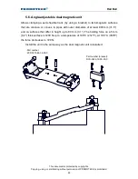
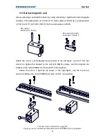
Page 20: ...he unit to a semi flexible rail as shown in the left figure use the 5 mm hex wrench to tighten the bracket to the unit with M6x20 screws and 6 4 mm washers and then tighten the bracket to the rail with M6x16 screws and 6 4 mm washers Attach the unit to a rigid rail as shown in the right figure use the 5 mm hex wrench to tighten the unit with M6x40 screws and 6 4 mm washers Part number ZSP 0475 44 ...

Page 21: ...to a temperature of 100 C 212 F At 180 C 356 F the force decreases to 450 N Attach the unit to a semi flexible rail as shown in the left figure use the 5 mm hex wrench to tighten the bracket to the unit with M6x16 screws and then tighten the bracket to the rail with M6x16 screws and 6 4 mm washers Attach the unit to a rigid rail as shown in the right figure use the 5 mm hex wrench to tighten the u...

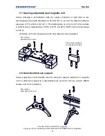
Page 22: ...rromagnetic surfaces that are concave or convex to pipes with outer diameters of at least 800 mm 31 5 and on surfaces that differ in height up to 80 mm 3 1 The holding force on a 5 mm 0 2 thick surface is 1200 N up to a temperature of 100 C 212 F At 180 C 356 F the force decreases to 720 N Install the unit in the same way as the dual magnetic unit is installed Part number ZSP 0475 85 00 00 0 Part ...

Page 23: ...230 mm 6 7 9 1 The holding force on a 5 mm 0 2 thick surface is 1200 N up to a temperature of 100 C 212 F At 180 C 356 F the force decreases to 720 N Install the unit in the same way as the dual magnetic unit is installed 5 8 Semi flexible track support Allows supporting a semi flexible track by using the support instead of a magnetic unit To attach the support to a semi flexible rail use the 5 mm...

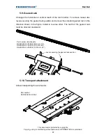
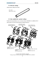
Page 24: ...securing the geared rack position and remove the standard geared rack in the direction shown in the figure Install in reverse order The teeth of the geared rack must be directed downward 5 10 Transport attachment Allows transporting the wire feeder Part number PEP 0482 18 00 00 0 Part number total length RAM 0475 07 01 00 0 300 mm 12 RAM 0475 07 03 00 0 700 mm 28 RAM 0475 23 00 00 0 1000 mm 39 Lev...

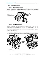
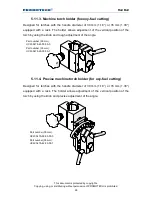
Page 25: ...gned for torches with the handle diameter of 28 35 mm 1 10 1 38 and enables precise adjustment of the torch angle The knob can be installed at each side after loosening the set screw with the 2 5 mm hex wrench and is used to adjust the vertical position of the torch To adjust the resistance of the vertical motion use the 2 5 mm hex wrench to unscrew all fixing screws and use the 2 mm hex wrench to...

Page 26: ...e vertical position of the torch by using the knob and rough adjustment of the angle 5 11 4 Precise machine torch holder for oxy fuel cutting Designed for torches with the handle diameter of 30 mm 1 18 or 35 mm 1 38 equipped with a rack The holder allows adjustment of the vertical position of the torch by using the knob and precise adjustment of the angle Part number 30 mm UCW 0475 61 00 00 0 Part...

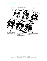
Page 27: ...mperial versions 2 3 manifold with cut off valve metric RZD 0475 66 00 00 0 3 3 manifold with cut off valve metric RZD 0475 72 00 00 0 1 4 RH 2 2 manifold metric RZD 0475 64 00 00 0 2 3 manifold metric RZD 0475 63 00 00 0 2 2 manifold with cut off valve metric RZD 0475 65 00 00 0 3 3 manifold metric RZD 0475 74 00 00 0 1 4 RH 1 4 RH 1 4 RH 1 4 RH 1 4 RH 1 4 RH 1 4 RH 3 8 LH 3 8 LH 3 8 LH 3 8 LH 3 ...

Page 28: ...anifold with cut off valve imperial RZD 0475 71 00 00 0 2 2 manifold imperial RZD 0475 68 00 00 0 2 2 manifold with cut off valve imperial RZD 0475 70 00 00 0 3 3 manifold imperial RZD 0475 73 00 00 0 9 16 RH 9 16 RH 9 16 RH 9 16 RH 9 16 RH 9 16 RH 9 16 RH 9 16 RH 9 16 LH 9 16 LH 9 16 LH 9 16 LH 9 16 LH 9 16 LH 9 16 RH 9 16 RH 9 16 RH 9 16 RH 9 16 RH 9 16 RH 9 16 LH 9 16 LH 9 16 LH 9 16 LH 9 16 LH...

Page 29: ...OMOTECH is prohibited 29 5 14 Vacuum track fixing system Dedicated to fixing the track to non ferromagnetic surfaces Part number vacuum pump with safety reservoir AGR 0541 10 10 00 0 115 V UK AGR 0541 10 20 00 0 230 V CEE Information about the other elements of the system are included in a separate manual ...

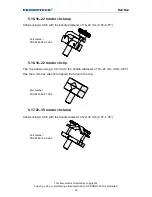
Page 30: ... handle diameter of 16 22 mm 0 63 0 87 5 16 16 22 mm torch clip The clip allows using a torch with the handle diameter of 16 22 mm 0 63 0 87 Use the 4 mm hex wrench to tighten the torch in the clip 5 17 22 35 mm torch clamp Allows using a torch with the handle diameter of 22 35 mm 0 87 1 38 Part number ZRZ 0466 19 00 00 0 Part number ZRZ 0466 04 01 00 0 Part number ZCS 0476 06 01 00 0 ...

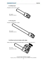
Page 31: ...TECH is prohibited 31 5 18 Short rod Provides a 120 mm 4 7 reach 5 19 Long rod Provides a 240 mm 9 4 reach 5 20 Short rod torch holder with clamp Allows using a torch with the handle diameter of 16 22 mm 0 63 0 87 Part number UCW 0476 20 00 00 0 Part number WLK 0476 20 01 00 0 Part number WLK 0466 04 10 00 0 ...

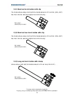
Page 32: ... 0 87 Use the 4 mm hex wrench to tighten the torch in the clip 5 22 Short rod low torch holder with clip The holder allows using a torch with the handle diameter of 16 22 mm 0 63 0 87 Use the 4 mm hex wrench to tighten the torch in the clip 5 23 Long rod torch holder with clamp Allows using a torch with the handle diameter of 16 22 mm 0 63 0 87 Part number UCW 0466 04 00 00 0 Part number UCW 0476 ...

Page 33: ...r distributing without permission of PROMOTECH is prohibited 33 5 24 Long rod torch holder with clip The holder allows using a torch with the handle diameter of 16 22 mm 0 63 0 87 Use the 4 mm hex wrench to tighten the torch in the clip Part number UCW 0466 22 00 00 0 ...

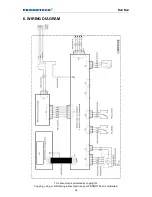
Page 34: ...Rail Bull This document is protected by copyrights Copying using or distributing without permission of PROMOTECH is prohibited 34 6 WIRING DIAGRAM ...

Page 35: ...nformity We PROMOTECH sp z o o ul Elewatorska 23 1 15 620 Białystok Poland declare with full responsibility that Rail Bull Welding Carriage is manufactured in accordance with the following standards EN 50144 1 EN 60974 10 and satisfies safety regulations of the guidelines 2004 108 EC 2006 95 EC 2006 42 EC Białystok 21 January 2013 ___________________________ Marek Siergiej CEO ...
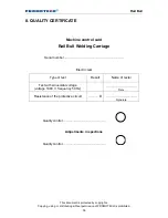
Page 36: ... prohibited 36 8 QUALITY CERTIFICATE Machine control card Rail Bull Welding Carriage Serial number Electric test Type of test Result Name of tester Test with sinusoidal voltage voltage 1000 V frequency 50 Hz Date Resistance of the protective circuit Ω Signature Quality control Adjustments inspections Quality control ...

Page 37: ... of defects in material and workmanship under normal use for a period of 12 months from the date of sale This warranty does not cover guiding rollers as well as damage or wear that arise from misuse accident tempering or any other causes not related to defects in workmanship or material Date of production Serial number Date of sale Signature of seller 1 05 12 September 2016 WE RESERVE THE RIGHT TO...

Reviews: