SECTION 5
Pronar T285/1
5.29
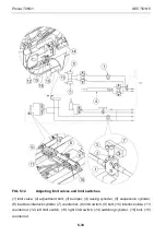
(5) of suspension interlock and load box hydraulic interlock (6). After adjustment, secure
adjustment bolts with counternuts (7).
Activation of limit switch (8) should be regulated by means of bolt (9). When slides (10) of the
interlock are slid together, the limit switch (8) must be pressed. After adjustment, secure bolt
(9) against unscrewing by means of counternut (11). Attach electric wiring harness to the
cylinder with band clips in such a manner as to prevent damage to the wiring harness.
Activation of limit switches (12) (13) of switching cylinder (14) should be adjusted by means
of bolts (15).
Right limit switch (13) must be pressed when the trailer is set to "hook trailer" position – in
this position, appropriate light located on the indicator plate must be switched on – figure
(3.3).
Left limit switch (12) must be pressed when the trailer is set to "tipper" position (switching
cylinder is maximally extended) – in this position, appropriate light located on the indicator
plate must be switched on – figure (3.3). After adjustment, secure adjustment bolts (15) with
counternuts (16).
Summary of Contents for T285/1
Page 2: ......
Page 6: ......
Page 11: ...SECTION 1 BASIC INFORMATION ...
Page 26: ...Pronar T285 1 SECTION 1 1 16 ...
Page 27: ...SECTION 2 SAFETY ADVICE ...
Page 42: ...Pronar T285 1 SECTION 2 2 16 ...
Page 43: ...SECTION 3 DESIGN AND OPERATING PRINCIPLE ...
Page 64: ...Pronar T285 1 SECTION 3 3 22 ...
Page 65: ...SECTION 4 CORRECT USE ...
Page 91: ...SECTION 5 MAINTENANCE ...
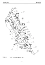
Page 124: ...Pronar T285 1 SECTION 5 5 34 FIG 5 13 Trailer s lubrication points part 1 ...
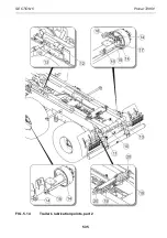
Page 125: ...SECTION 5 Pronar T285 1 5 35 FIG 5 14 Trailer s lubrication points part 2 ...
Page 134: ...Pronar T285 1 SECTION 5 5 44 ...
Page 135: ...NOTES ...
Page 136: ......


