4.2
4.1
PREPARING FOR WORK BEFORE FIRST USE
The trailer is supplied to the user in a completely assembled state and does not require
additional mounting operations of machine sub-assemblies. The manufacturer guarantees
that the trailer is fully operational and has been checked according to quality control
procedures and is ready for normal use. This does not release the user from an obligation to
check the machine's condition prior to purchasing and before first use.
Prior to connecting to the tractor, machine operator must verify the trailer's technical
condition. In order to do this:
•
the user must familiarise himself with the content of these instructions and observe all
recommendations
•
immobilise trailer with parking brake,
•
check condition of paint coatings, traces of corrosion or mechanical damage (crushing,
piercing, bending or breaking of minor elements),
•
Check if side walls open correctly, locks interlock properly, there are no missing cotter
pins,
•
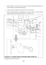
Check if tipping pins are inserted and correctly interlocked (pin lug should be vertical,
cotter pin installed),
•
check air pressure in tyres and check correct tightening of wheel nuts,
•
check if the drawbar is correctly installed,
•
Check the technical condition of canvas cover, clips fastening canvas belts and if the
frame is assembled correctly.
•
Drain water from pneumatic system -- see section 5.
If all the above checks have been performed and there is no doubt as to the trailer's good
technical condition, it should be hitched to tractor (4.3). After connection of brake system
conduits and hydraulic tipping system conduit, the correct operation of individual systems
should be checked with inspection of systems and hydraulic cylinders with regard to seals
and tightness. Further use of the trailer, is not permitted, if there are any leaks from hydraulic
systems or if the brake systems are unreliable. If any faults are detected they must be
Summary of Contents for T780
Page 2: ......
Page 5: ......
Page 17: ...1 10 ...
Page 43: ...3 14 ...
Page 72: ...5 13 DRAWING 5 6A CHASSIS GREASING POINTS ...
Page 73: ...5 14 DRAWING 5 7A LOAD BOX GREASING POINTS ...
Page 80: ...5 21 ...
Page 81: ...NOTES ...
Page 82: ... ...


