26
90
I 1 ~ I 5
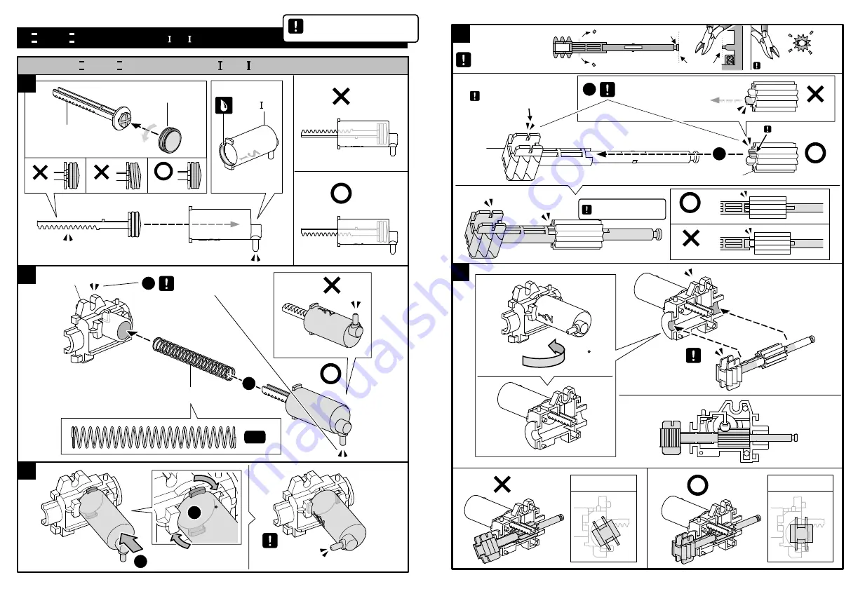
液 壓 筒 組 裝
I 1 ~ I 2
液 壓 筒 組 裝
1
2
3
1
2
2
A6
P13
E27
P7
1
2
注意零件方向
注意零件方向
推入
重要操作,請特別注意
1:1
1 & 2 Cylinder
1 ~ 5 Cylinder Assembly
PUSH
PUSH
Ensure the right direction
Ensure the right direction
Important
27
5
4
E23
E18
E18
2
注意零件方向
注意零件方向
前視圖
前視圖
1
組裝前請先剪除毛邊
非常小的凹槽朝上
剪到虛線處
不要剪到連接柱
注意!開口朝上
180
E23
組裝前請先剪除毛邊
重要操作,請特別注意
Front View
Front View
Ensure the right direction
Cut off the burrs before assembly.
Cut off the burrs before assembly.
The smallet groove faces up.
Cut here at line.
Don’t cut.
Notice
!
Open slot face up.
Important
Ensure the
Right direction
Summary of Contents for GE-632
Page 1: ...GE 632 Hydraulic Robot Arm...
Page 6: ...8 3 P2 1 1 9 P2 4 5 1 2 1 2 E16 G6 1 1...
Page 9: ...14 4 D2 D3 P2 P2 5 E13 180 1 1 15 6 7 P2 C9 G10 D4 P2x2 1 1 2 E26 Forearm Wrist...
Page 17: ...30 E20 12 14 13 2 2 1 1 P8 C19 Side View PUSH PUSH 31 A7 1 1 2 15...
Page 28: ...52 3 2 3 1 click click click click Push 53 4 5 6 1 2 H0 3 PUSH PULL Cylinder PUSH PUSH...
Page 31: ...58 3 2 1 3 click click click click PUSH PUSH 59 4 5 6 1 2 3 PUSH PULL PUSH PUSH...
Page 34: ...64 3 2 3 1 Click Click Push 65 5 4 6 1 2 3 PUSH PULL PUSH...
Page 37: ...70 10 1 2 Marking 71 2 1 11 12 4 3 Cylinder Ensure the right direction...


