background image

目次頁

產品介紹

自備工具

零件清單

塑膠模型零件

組裝說明

夾頭組裝

控制盤組裝

手臂組裝

液壓油使用說明

H0~H5

液壓筒組裝

I

1~ 

I

5

液壓筒組裝

軟管裁切

液壓筒填充說明

軟管與液壓筒組裝

液壓筒模組組裝

操縱桿組裝

控制盤與液壓筒模組組裝

液壓筒與手臂組裝

操作方式

簡易故障排除

P.1

P.1

P.2

P.3

P.6

P.7

P.13

P.20

P.20

P.26

P.35

P.36

P.37

P.37

P.49

P.51

P.66

P.76

P.86

Tools You May Need

Product Introduction

Plastic Parts

Lever Controller Assembly 

Mechanical Assembly

Gripper Unit Assemily 

H0~H5 Cylinder Assembly

Stand & Control Base Assemily

Main Body Assembly

How To Oil The Parts

How To Cut The Tube

How To Fill Up The Cylinder With Water

How To Fit Tube   

Hydraulic Cylinder Module Assembly

1 ~   5 Cylinder Assembly 

Robot Arm Module Assembly 

Controller Module Assembly 

How To Play

Trouble Shooting

Mechanical

1

0

1

2

3

4

5

6

7

8

9

10 11

12 13 14 15 16 17 18 19 20                                                

21 22 23 24 25 26 27 28 29 30

CM

or

液 壓 機 器 手 臂

Hydraulic Robot Arm

產 品 介 紹

Product Introduction

With Hydraulic Arm Edge, command six axes of varied movements: the gripper to open and close up to 1.89 

inches, wrist rotation of 180 degrees, wrist mobility of 98 degrees, elbow range of 44 degrees, base rotation of 

270 degrees, and shoulder motion of 45 degrees. With a vertical reach of 16.35 inches, horizontal reach of 12.42 

inches, and lifting capacity of 50g, your robotic friend is ready for your genius to erupt. With the removal of the 

gripper, you can activate the suction apparatus. This feature enables the user to elevate objects with a larger 

surface area (like a small mobile phone). Another prodigious attribution is a braking system that is integrated in 

the lever controllers to execute all commands accurately. WOW!
How does this equate to fun? Your children will have total command and visual manipulation using the science 

principles of a Hydraulic system and its application. Easy to follow instructions with detailed graphic illustrations 

pave the way for successful and satisfying kit building. Compliment your engineering, math, science, and    

technology learning strategy.  No battery or motor required. It is powered by water; thus, the “Hydraulic” 

significance and how it manipulates axes movement via lever controllers. Hydraulic  Arm Edge is recommended 

for ages 10 and up, but with its 229 assembly parts, it will challenge the beginner engineering enthusiasts. 

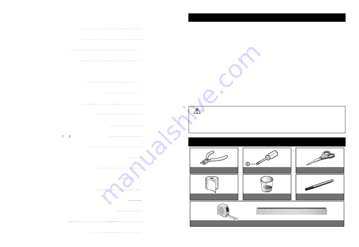
自 備 工 具 如 下

Tools You May Need

斜 口 鉗

Diagonal Cutter

剪 刀

Scissors

面 紙

Tissue Paper

十 字 起 子

Screwdriver

杯 子 和 水

Cup & Water

捲 尺 或 尺

Tape Measurer   or   Ruler

油性麥克筆(細字)

Marker Pen (Fine)


1.本玩具內含小物件,請勿讓三歲以下孩童取得,以免放入口中造成窒息。

2.兒童使用剪切工具時,請家長指導使用方式,並請在家長監督下使用,以免發生意外。

3.為避免嬰兒或兒童產生窒息的危險,請於拆卸後立即將塑膠袋銷毀或遠離嬰兒及兒童。

Choking hazard -  Small parts. Not for children under 3 years.

Adult supervision is recommended when children use scissors.

To avoid danger of suffocation, keep the plastic bag away from babies and children.

Warning

歡迎購買寶工

GE-632

液壓機器手臂。這是一款使用液壓方式操作的玩具,六軸設計液壓手臂可做出多種動

:

前端夾具可進行開闔動作,最大開口約

4.6cm

,可旋轉

180

˚

,手腕可上下移動

98

˚

,肘部上下移動

44

˚

肩部上下移動

45

˚

,底座可左右旋轉

270

˚

,手臂可上舉的最大高度約

42cm

,水平伸展約

32cm

,可夾舉重量

50g

。卸下夾具後,還可使用吸盤裝置,吸盤設計不受物體大小限制,可吸取面積更大的物體。本產品由

229

個零件組成,組裝說明沒有多餘的文字敘述,詳細的圖示就可輕鬆組裝,同時可了解液壓原理,組裝後

可實際操作應用,透過操縱桿使六軸動作配合無間,訓練手眼協調。不須電池、不須馬達、水就可驅動一
切,歡迎工程系列愛好者挑戰本進階模型。推薦

10

歲以上兒童可嘗試獨立組裝,父母在旁陪伴,兒童可從

中得到自我滿足的成就感,同時快樂的享受親子共遊的樂趣。

Summary of Contents for GE-632

Page 1: ...GE 632 Hydraulic Robot Arm...

Page 2: ...e gripper you can activate the suction apparatus This feature enables the user to elevate objects with a larger surface area like a small mobile phone Another prodigious attribution is a braking syste...

Page 3: ...ake Pad Cap Small Iron Bar Long Tapping Screw Long Cap Big Suction Cup Sponge Spring Smallest Spring Short Spring Medium Spring Long 3 P14 P15 1 pc 5 pcs 60cm 3 1 4 5 6 7 2 MIDE IN TAIWAN A A B C 10 5...

Page 4: ...IWAN 10 13 12 14 15 16 11 17 18 19 20 21 22 23 24 26 27 25 28 29 30 31 32 33 Spare Part 5 G H MIDE IN TAIWAN G 7 8 9 6 12 16 15 14 18 19 17 13 11 10 G 1 G 2 G 3 G 5 G 4 H MIDE IN TAIWAN H5 H4 H0 H1 H3...

Page 5: ...6 2 1 2 3 1 2 D7 C2 C4 C5 D6 P2 C3 1 P9 C2 C3 E3 G12 Gripper Unit Assembly Cut off the burrs before assembly Cut off the burrs before assembly 2 7 F2 B F5 F1 1 2 P2 Stand Control Base Assembly 1 1...

Page 6: ...8 3 P2 1 1 9 P2 4 5 1 2 1 2 E16 G6 1 1...

Page 7: ...10 6 7 PUSH G11 2 P9 2 P9 2 P9 2 P9 3 P9 x4 G11 PUSH PUSH You will hear G11 snap into place when you push down far enough 11 8 9 1 1 2 2 2 G18 G17 P4 P3 P1 P1 E2 G8 1 Free Rotation 1 1...

Page 8: ...12 10 1 2 E25 F4 Control Base Stand 13 F7 D5 G16 1 2 3 P2 P1 E14 C18 F3 Main Body Assembly 1 1 1 1...

Page 9: ...14 4 D2 D3 P2 P2 5 E13 180 1 1 15 6 7 P2 C9 G10 D4 P2x2 1 1 2 E26 Forearm Wrist...

Page 10: ...16 8 9 2 2 2 2 3 3 3 3 E15 P1x4 G13 G14 E15 D1 1 1 1 Ensure the right direction Ensure the right direction 1 1 17 11 10 1 E11 P2x4 P1 E8 2 3 E1 Wrist Forearm 1 1 1 1...

Page 11: ...18 12 Arm Stand Control Base Forearm Wrist 19 E10 12 P1 E10 P1 E10 Cut off the burrs before assembly Bottom View Bottom View Make sure E10 is not inserted upside down...

Page 12: ...the G9 oil sink Keep oil contained H 0 H0 Cylinder Assembly H 0 H 5 H0 H5 Cylinder Assembly Do not oil outside the shadow as shown below Note Oil the parts when appears Apply Oil Cylinder 21 H 1 1 3 2...

Page 13: ...22 H 2 H2 Cylinder Assembly G2 G2 1 3 1 2 E7 P7 C21 C20 H2 2 4 H2 Important Cylinder Click Click 23 H 3 2 4 G3 1 3 1 2 E7 P7 C21 C20 H3 G3 H3 Cylinder H3 Cylinder Assembly Important Click Click...

Page 14: ...24 H 4 2 4 G4 1 3 1 2 E7 P7 C21 C20 H4 G4 H4 Important H4 Cylinder Assembly Cylinder Click Click 25 H 5 H5 Cylinder Assembly 2 4 G5 1 3 1 2 E7 P7 C21 C20 H5 G5 H5 Important Cylinder Click Click...

Page 15: ...ht direction Ensure the right direction Important 27 5 4 E23 E18 E18 2 1 180 E23 Front View Front View Ensure the right direction Cut off the burrs before assembly Cut off the burrs before assembly Th...

Page 16: ...28 1 1 6 8 7 9 10 A3 P7 A1 P11 E9 E12 2 3 1 1 90 1 2 E9 Cut off the burrs before assembly PUSH Back View 1 1 29 180 F6 11 A5...

Page 17: ...30 E20 12 14 13 2 2 1 1 P8 C19 Side View PUSH PUSH 31 A7 1 1 2 15...

Page 18: ...2 Suction Cup Cylinder Cylinder Very Important Cut off the burrs before assembly 33 I 3 I 4 4 Cylinder Important Important Click Click 1 P6 2 3 3 1 2 C15 C14 4 4 1 2 P6 1 2 E22 C10 3 3 C11 E24 Click C...

Page 19: ...r Click Click Important 35 1 2 3 4 P14 How To Cut The Tube Soft Tube Measuring Marking Cutting Coding Marker Pen Fine Use the same tube to cut Tube 1 Tube 0 8cm 3 15 inches 50cm 19 69 inches 56cm 22 0...

Page 20: ...with water 1 1 2 3 2 3 3 How To Fill Up The Cylinder With Water Cup Water Pour around a half cup of water Water Press down the piston to the bottom Fill up the cylinder with water when appears 37 1 H...

Page 21: ...entirely Press down the piston to the bottom Cylinder 39 1 3 4 2 H 4 I 4 42cm 4 H4 1 2 1 2 4 Press down the piston to the bottom Connect H4 With 4 Push to the end Pull up entirely Tube Cylinder Fill...

Page 22: ...ottom H 3 I 3 Connect H3 With 3 Push to the end Pull up entirely Tube Cylinder Fill up the cylinder with water Cylinder 41 1 3 4 2 H2 56cm 2 2 1 2 H 2 I 2 Connect H2 With 2 Push to the end Pull up ent...

Page 23: ...H 1 H 0 With 1 Tube Cylinder Pull up entirely Push to the end Fill up the cylinder with water 43 4 5 6 H0 1 2 50cm 1 0 H1 Tube Tube Cylinder Cylinder Push to the end Pull up entirely Press down the p...

Page 24: ...44 7 P12 P12 E4 E5 8 1 1 1 2 PUSH H0 Cylinder 1 1 PUSH PUSH 45 10 9 1 2 1 Push to the end Pull up entirely Cylinder...

Page 25: ...g Pictures below not to scale Cylinder Cylinder Cylinder 8 27 inches 8 66 inches 47 13 5 cm 11 cm H0 H1 H2 H3 8 5 cm 1 Tube 2 Tube 3 Tube Cylinder Cylinder Cylinder Cylinder 3 26 inches 5 31 inches 4...

Page 26: ...5 cm 5 5 cm 14 5 cm 2 17 inches 5 31 inches 6 10 inches 5 71 inches 49 G19 1 2 G19 G19 C1 P2 E29 P5 G19 P5 P5 10 5 Lever Controller Assembly Very Important P5 Brake Pad must be clean and not stained...

Page 27: ...troller 3 4 5 3 Big Hole Small Hole Big Hole Small Hole Big Hole Small Hole FRONT FRONT FRONT 51 1 2 1 1 P10 H1 2 Stand Control Base Control Module Assembly Ensure the right direction 1 H0 H1 1 Unit 1...

Page 28: ...52 3 2 3 1 click click click click Push 53 4 5 6 1 2 H0 3 PUSH PULL Cylinder PUSH PUSH...

Page 29: ...54 1 2 1 H2 P10 2 2 Ensure the right direction 2 H2 2 Unit 2 H2 Cylinder Lever Controller 2 Lever Controller 2 FRONT Front View Cylinder 55 1 2 3 3 Click Click Push...

Page 30: ...56 4 5 3 PUSH 1 2 6 PUSH PULL 57 1 1 2 H3 P10 2 3 Front View Ensure the right direction Cylinder 3 H3 3 Unit 3 H3 Cylinder Lever Controller 3 Lever Controller 3 FRONT...

Page 31: ...58 3 2 1 3 click click click click PUSH PUSH 59 4 5 6 1 2 3 PUSH PULL PUSH PUSH...

Page 32: ...60 1 2 1 P10 H4 2 4 Cylinder Ensure the right direction 4 H4 4 Unit 4 H4 Cylinder Lever Controller 4 Front View Lever Controller 4 FRONT 1 61 3 3 2 Click Click Push...

Page 33: ...62 4 5 6 1 2 3 PUSH PULL PUSH 63 1 2 1 P10 H5 2 5 Lever Controller 5 FRONT Ensure the right direction 5 H5 5 Unit 5 H5 Cylinder Lever Controller 5 Front View Cylinder...

Page 34: ...64 3 2 3 1 Click Click Push 65 5 4 6 1 2 3 PUSH PULL PUSH...

Page 35: ...66 1 2 1 Robot Arm Module Assembly Cylinder 2 Cylinder 67 3 4 5 Marking Marking Marking Marking...

Page 36: ...68 STRETCH 6 7 3 1 2 4 Marking Set the soft tube in the groove 69 8 9 A4 C7 C6 3 Top View Cylinder Don t Pull Inside View Inside View...

Page 37: ...70 10 1 2 Marking 71 2 1 11 12 4 3 Cylinder Ensure the right direction...

Page 38: ...72 13 14 1 2 3 C8 Marking Marking 73 15 16 5 PUSH 5 Cylinder Lever Controller 5 PUSH PUSH PUSH PUSH...

Page 39: ...your hand measure approx 4 finger width of soft tube this is to assist you in fixing E17 and binding the tubes 75 E17 19 20 3 1 2 4 5 2 3 1 E17 E17 Using your hand measure approx 4 finger width of so...

Page 40: ...76 Operate on a smooth and level surface Handle the arm with care and do not mistreat as shown above How To Play Warning 77 3 3 3 5 98 180 44 45 4 2 6 270 2 6 How To Play 2 6 AXES...

Page 41: ...78 1 1 1 2 1 How To Play Gripper Mode Installation Lever Controller 1 Pull Lever Controller 1 backward as above Gripper Unit Ensure the Right direction 79 3 4 Gripper Unit Ensure the right direction...

Page 42: ...er 1 forward Maximum Lift 50 g Release the object Pull Lever Controller 1 backward 81 1 2 3 1 2 How To Play Suction Mode Gripper Unit Release Gripper unit and put it aside as below Very Important Step...

Page 43: ...page 77 and have suction cup target the object Make suction cup stick to the object tightly To obtain the best results put suction objects on a smooth surface suction objects bigger than the suction...

Page 44: ...Controller 5 forward to lift the object Set Lever Controller 1 in the middle to release object 85 8 Tip Put the object under a slightly higher and smoother platform it may help you practice the Suctio...

Page 45: ...5 I3 4 5 3 4 5 37 40 2 If operation angle on the Axes 3 4 5 is unable to extend to the max Poor movement of the 6th Axe Check if there is excess air inside the Cylinder H3 4 5 3 4 5 and Tube 3 4 5 in...

Page 46: ...ng Long Soft Tube Oil Bag Plastic Part A Plastic Part B Plastic Part C Plastic Part D Plastic Part E Plastic Part F Plastic Part G Plastic Part H I 1 E mail Name address no P O Box telephone number an...

Reviews: