background image


708E Series User Manual


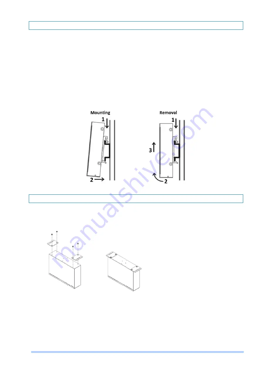
2.2  DIN-rail Mounting 


The DIN-rail mounting is only for the 708EPI-DC. 


Mounting Step 

STEP 1: Hook the unit over the DIN-rail.   

STEP 2: Push the bottom of the unit towards the DIN-rail until it snaps into place.   


Removal Step 

STEP 1: Push the unit down to free the bottom of the DIN-rail.   

STEP 2: Rotate the bottom of the unit away from the DIN-rail. 

STEP 3: Unhook top of unit from DIN-rail. 


2.3  Wall Mounting 

The wall mounting is only for the 708EPI-DC. 

STEP 1: At the bottom side of the device, use two screws to install each bracket.   

NOTE: Each screw type is flat head M3 x 4 mm. 


STEP 2: Use the screws to attach the bracket of the device for wall mounting. 

NOTE: These screws are not included in the package. The head of each screw is less than 7 mm in 
diameter, the shaft is less than 3 mm in diameter, and the length is less than 10 mm in diameter. 

Summary of Contents for 708E Series

Page 1: ...708E Series 8 Port PoE Long Reach Switch Extender User Manual Version 1 00...

Page 2: ...7 LED Definition 8 3 1 LED Indicators 8 Power Connection 9 Ground Connecting 9 Web Management 10 6 1 Access the Web Configurator 10 6 2 Web Interface 11 6 2 1 Information 11 6 2 2 Status of Interface...

Page 3: ...dant long distance power cabling each 101EPI receives power from any port of the 708E Series and offers 802 3at Power over Ethernet for the remote devices such as IP cameras With the intelligence of b...

Page 4: ...AC Dimensions W x H x D 404 x 44 5 x 177 mm Weight 2 34 kg Rack Mounting Power 708EPI DC Power Input 55 57VDC System power consumption 10W PoE power budget 200W 708EP AC Power Input 100 240VAC 60 50H...

Page 5: ...meters 10Mbps 18 0 700 meters 10Mbps 8 0 800 meters 10Mbps 15 5 800 meters 10Mbps 6 5 900 meters N A N A 900 meters N A N A Cat 6 UTP 4 Pairs 708EP AC 25 C PoE Power Budget 188W Cat 6 UTP 2 Pairs 708...

Page 6: ...ring Information Model Name Description 708EPI DC 8 Port PoE Long Reach Switch Extender DC power input 708EP AC 8 Port PoE Long Reach Switch Extender AC power input NOTE Features and specifications ar...

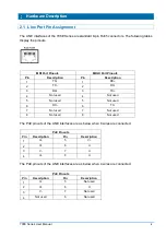
Page 7: ...X 1 RX 2 TX 2 RX 3 RX 3 TX 4 Not used 4 Not used 5 Not used 5 Not used 6 RX 6 TX 7 Not used 7 Not used 8 Not used 8 Not used The PoE pinouts of the LINE interfaces are as below when 8 wires are connec...

Page 8: ...om of the unit away from the DIN rail STEP 3 Unhook top of unit from DIN rail 2 3 Wall Mounting The wall mounting is only for the 708EPI DC STEP 1 At the bottom side of the device use two screws to in...

Page 9: ...tch and fasten the mounting kits by using screws NOTE The type of screw is flat head M3 x 5mm STEP 2 After attaching two brackets line up the rack mounting positions of the holes in the brackets with...

Page 10: ...nking Device Error PoE1 8 Green On Powered Device Connected Off Powered Device Disconnected UPLINK Green On 1000Mbps UPLINK LINK UP Off 1000Mbps UPLINK LINK DOWN Blinking 1000Mbps Data Transmitting Ye...

Page 11: ...negative wires into V and V contact on the terminal block and tighten the wire clamp screws to prevent the wires from being loosened For 708EP AC Use the included power cord to connect the power socke...

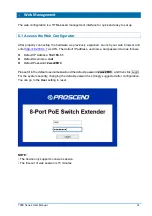
Page 12: ...8 1 1 as URL The default IP address username and password are as follows Default IP Address 192 168 1 1 Default Username root Default Password 2wsx EDC Please fill in the default username root and the...

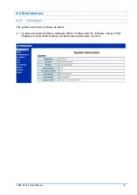
Page 13: ...ual 11 6 2 Web Interface 6 2 1 Information The system information is shown as below 1 System shows Model Name Hardware MCSV Software MCSV Software Version PSE Software Version MAC Address Serial Numbe...

Page 14: ...PSE Port Status 1 The setting of Refresh Interval allows you to set up how long the information status is updated 2 The Switch Port Status includes Broadcast Multicast Unicast status and Link Status...

Page 15: ...power The following table lists the different classes according to power at PSE output and PD input Class Usage Classification current mA Power range at PD W Max power from PSE W Class description 0...

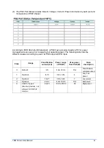
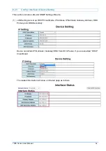
Page 16: ...N and SNMP Setting of Device 1 LAN Setting can set up DHCP Client Mode IP Address IP Netmask Gateway Address DNS Primary and DNS Secondary Device can obtain IP Netmask Gateway DNS from DHCP server if...

Page 17: ...n the event of link up or link down the switch will automatically send the TRAP packet to destination address NOTE The SNMP Trap is supported SNMP V1 only NOTE The SNMP Trap supports 6 2 4 Config Port...

Page 18: ...rs 100Mbps 23 5 500 meters 100Mbps 12 0 600 meters 10Mbps 21 5 600 meters 10Mbps 10 0 700 meters 10Mbps 18 0 700 meters 10Mbps 8 0 800 meters 10Mbps 15 5 800 meters 10Mbps 6 5 900 meters N A N A 900 m...

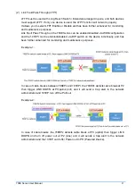
Page 19: ...on and the 101EPI can be enabled disabled via DIP switch on the device individually and has been further enhanced for monitoring and maintenance purposes Example 1 In case of cable breaks between 708E...

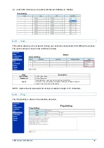
Page 20: ...The users setting is shown in the interface as below Item Description User name Enter user name Password Enter Password Level Administrator user can setup and read anything Normal user can setup and...

Page 21: ...e ready to load or not 6 2 8 Upgrade The Device provides a TFTP server for User upgrade software via TFTP client This can be done through Ethernet You can update the new firmware via TFTP upgrade tool...

Page 22: ...708E Series User Manual 20...

Page 23: ...fter clicking Reboot item it will be shown the interface as below to make sure if you are ready to reboot or not 6 2 10 Logout Logout the device After clicking Logout item it will be shown the interfa...

Page 24: ...All electric installations must be carried out in accordance with local and national regulations Do not work on the system connect or disconnect cables during periods of lightning activity The equipme...

Reviews: