10
PRS-UM-BTN-EN-Rev02-02.2019
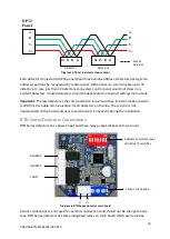
Diagram 5: Panel to detector connections
Each detector connected to DP32 panel should have unique address. Detectors having same
address would not be recognised by control panel. DP32 panel can communicate up to 32
detectors. In case less then 32 detectors connected, control panel would not show non-
existent detectors. Unused detectors should be deactivated on channel settings menu steps.
Important:
The last detector at the communication line should have line termination resistor
(120 Ohm) to enable communication for all detectors on the line. The resistor is not
implemented on the board and user should connect it physically during the installation.
BTN Series Detectors Connections
BTN Series detectors has a power input and three relay output sockets on main board.
Diagram 6: BTN Series detector main board
Sensor connections are not used for external connections and should not be changed in any
case. BTN Series detectors has three integrated relays on main board which are named as
Detector 1
Detector 2
A
B
V-
V+
DP32
Panel
Max 32
Detector
V+ V- B A
V+ V- B A
A
B
V-
V+
V- V+
ALARM1
FAULT
Sensor connection
Address and alarm level
adjustment switches
ALARM2


