13
PRS-UM-BTN-EN-Rev02-02.2019
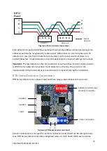
given to them. The address of detector can be adjusted via using DIP-Switch set on the board:
Diagram10: RS485 Modbus serial communication address and switch position
Important
: Only the last detector on the serial bus should have end of line resistor.
System Status
Prosense BTN Series detectors has two LEDs on main board. Red LED shows system power
status and yellow LED shows fault status. Both LEDs will start blinking right after power
applied. After appoximitly 90 sec the yellow LED will be turned of and only red LED will
continue blinking. This status means that detector is ready to normal operation.
First time switch on (Commissioning)
WARNING
The following procedure requires the detector cover to be removed while carrying out supply
voltage checks. Therefore the appropriate permits to work should be sought in preparation.
Prior to carrying out any HOT WORK ensure local and site procedures are followed. Ensure
that the associated control panel output actuation is inhibited so as to prevent false alarms.
Caution: The following procedure should be followed carefully and only performed by
suitably trained personnel
1.
Remove the detector cover
2.
Make sure the detector's output and power input connections done correctly
3.
Check that all electrical connections are terminated correctly


