14
PRS-UM-BTN-EN-Rev02-02.2019
4.
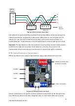
Switch On the external power supply to feed the detector. If it is connected to DP32 Panel,
cables should be installed according to DP32 Panel user manual as panel can provide both
power and communication connections to the detectors.
5.
Using a Digital Multi Meter (DMM), check the Supply Voltage at the terminals V+ and V-
this should be a minimum supply voltage of 12VDC (Maximum supply voltage is 24VDC).
6.
Check LED status on detector main board. LED status should be like explained above after
appying power depending of the detector model.
7.
Wait two minutes and confirm detector LED status pointing normal operation. If detectors
used with DP32 Panel, panel should recognise each detector correctly at their addresses.
8.
Switch Off the external power to the detector.
9.
Fit the cover and make sure non of the cables cause an obstruction while fitting cover
10.
Switch on external power to the detector or panel if used.
Calibration
It is recommended to periodically carry out calibration to ensure correct operation.
Calibration should be done by a person who trained and certified by local or international
authorities.
Detector should be powered and stabilized for at least 30 minutes before calibration. For
Flammable gas calibration use a calibration gas concentration of between 25%LEL and
75%LEL to ensure that the required accuracy can be attained. To calibrate the detector, use
an appropriate span gas cylinder, constant flow regulator and Prosense Gas Cap. The flow
rate used for calibration gas is 0.5 L/Min.
Important:
Any optional board is installed on detector should be removed prior the
calibration as some of the features masked or unavailable with them when installed.
Zero Calibration
It is recommended to use a compressed air cylinder (20.9%Vol oxygen) to perform the zero
calibration if the area where the detector is located contains any residual amount of the
target gas. If no residual gas is present then the background air can be used to perform the
zero calibration. To perform Zero calibration put a jumper to Z pins on detector main board
and press Zero button for 3 seconds. The zero level will be automatically adjusted.
Span Calibration
As there is only relay outputs and RS485 communication ports availabale on detector it is
necesssary to use a control panel to see gas measurement of the detector during the span
calibration. If RS485 communication is not possible calibration should be done ina service
center. To perform Span calibration apply gas to detector via using the Gas Cap while
detector is energised and working. The signal level vary depending on the used gas for
calibration and gas concentration. If the measured level is lower than the calibration gas
level, put a jumper to S+ pin press to Span button till the level reaches the necessarly value.
If the measurement level is higher than the necessary value, put a jumper to S- pin and press


