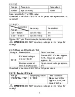
measuring the high voltage circuit.
6. Do not input more than 250V DC or AC peak value to avoid
damaging the instrument.
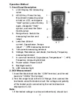
9. .Diode and Continuity Test
1. Insert the black lead into “COM” terminal, and red lead into
“V/
Ω
/Hz” terminal (Note: the polarity of red lead is positive)
2. Turn the knob to the “
” Range, then connect the test
leads across the tested diode, the reading is the
approximation of the diode forward voltage drop.
3. Connect the test leads to the two points of the tested circuit,
if the value of resistance between the two points is less
than (70±20)
Ω
, the buzzer inside sounds
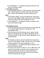
10. Temperature Measurement
When measuring Temperature, input the negative pole of
the thermocouple sensor into “COM” terminal, and positive
pole into “mA” terminal, connect the working side of the
thermocouple to the surface or inside of the tested subject,
to read the Fahrenheit temperature from LCD directly.
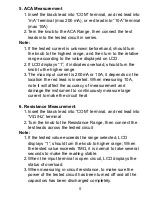
11. TRIODE hFE
1. Set the range knob to hFE.
2. Insert the test accessory into “
COM
” and “
mA
” terminal.
3. Verify the type of the transistor is NPN or PNP, insert the
emitter, basic and collector to the proper jack on test
accessory.
12. Data Hold
Press the HOLD key, the present data is held on LCD.
13. Auto Power Off
Stop working around 15 minutes, the instrument will auto
off and get into the sleeping mode.
10


