9
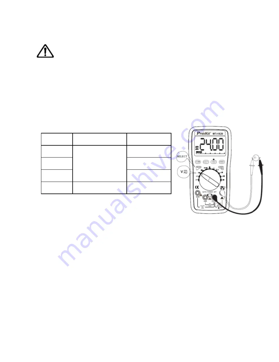
the red test lead and the tested voltage value will be displayed on
LCD simultaneously
Note:
a) Do not measure the voltage higher than DC 1000V or AC 750V.
b) When measuring the high voltage, caution to avoid electric shock.
Cut the connection between the test lead and tested circuit at once
after measurement.
C) At the Manual Range mode, if “OL” is displayed on LCD, it
indicates the tested voltage value has exceeded the present range
limit, please select the higher range to complete the measurement
Range
Accuracy
Resolution
6V
±(0.8%+10d)
1mV
60V
10mV
600V
100mV
750V
±(1.0%+10d)
1V
Input impedance: 10MΩ. Overload
protection : 1000V DC or 750V AC peak
value.
Frequency response: 40-400Hz. Indication: average value
response (RMS of sine wave).
Duty Circle indication (0.1%~99.9%)
DC Current (DCA)
1. Insert the black test lead to “COM” input terminal and the red test
lead to “mA ”or “10A”, displayed as the picture.
2. Turn the function/range selection knob to current range, press
“SELECT”, switch to DC measurement mode, then connect the test
lead with the tested circuit in series, the polarity of the red test lead
and the tested current value will be displayed on LCD
simultaneously.
Summary of Contents for MT-1820
Page 26: ...25 MT 1820 3 5 6 USB 24mm LCD 61 REL USB LCD 4 A D K USB MT 1820 IEC1010 2...
Page 27: ...26 30V 10mA 2 3 4 5 6 7 8 9 10 11 12 LCD 13 14...
Page 28: ...27 1 2 61 LCD 3 RANGE 2 fHE 4 HOLD 5 Hz DUTY 6 MAX MIN MAX MIN MAX MIN 2 MAX MIN...
Page 36: ...35 400mV 250V 2 V Hz COM SELECT 3 4 a OL b c 250V 1 0mA 3 0V 50 0 5V...
Page 39: ...38 1 hFE 2 mA COM 3 NPN PNP E B C 4 a mA COM b hFE NPN PNP 0 1000 1mA VCE 2 1V...
Page 41: ...40 1 USB USB 2 COM5 3 OPEN COM 4 USB2 0 1 2 START 3 HELP 1 2 20 3 4 1...
Page 42: ...41 2 3 4 5 LCD a b 2 1 5V 1 5V c d 1 1000V 2 3 4...
Page 43: ...42 MT 1820 12 CD 0755 83692415 83692986 83246594 83247554 0755 83692143...
Page 44: ...43...


