background image

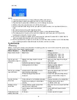
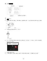
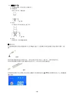
  Fig.8 

4. 

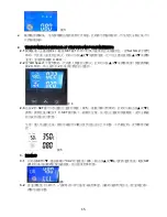
When the status display under temperature is "L” or “L L"(Fig. 9), it means temperature has been 

calibrated and decreased before. 

  Fig. 9 

5. 

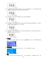
When the status display under temperature is "HHH"(Fig. 10), it means temperature has been 

calibrated to max. temperature, which can not be increased but only decreased. 

  Fig. 10 

6. 

The status display under temperature is "LLL"(Fig. 11), it means temperature has calibrated to 

minimum temperature, which can not be decreased but only increased.. 

  Fig. 11 


Fahrenheit and Centigrade Selection 

Press the 

“SET” button and turn on the power switch to power on the station as Fig.12, and switch the 

temperature display from 

  to 

  by pressing the UP 

  or Down button 

. After selection, press 

“SET” button to confirm and back to the main menu 

  Fig.12 


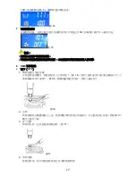
Reset 

Press the UP 

  and DOWN 

  button in the same time, rework station will be back to the initial 

setting; after one second, LCD screen be back to the standby mode(Fig.13). 

  Fig.13 

Summary of Contents for SS-956

Page 1: ...SS 956 SMART REWORK STATION WITH VACUUM PICKUP User s Manual 1st Edition 2017 2017 Copyright by Prokit s Industries Co Ltd...

Page 2: ...from indoor temperature to 480 C 896 F To avoid injury to personnel or damage to items in the work area observe the following Do not direct the hot air toward personnel or touch the metal parts near t...

Page 3: ...nsor design switches work sleep mode for real time operation convenience Provide 600W high power and wide temperature range up to 480 C Auto cool off process to prolong the lifetime of heating element...

Page 4: ...to Cool Off Function YES Equipment Noise 50dB Temperature Display LCD 60mm X 35mm Backlight Fuse 5A 250V 5x20mm 8A 250V 5x20mm Power Plug B H E Heating Element Model No 5SS 989NB H 5SS 989NE H Hot Air...

Page 5: ...g 3 When lift the hot air gun LCD screen will display the last setting temperature Fig 3 6 Do not unplug the power plug instantly after turning off the power switch because the fan will keep operating...

Page 6: ...rature or air speed by using the UP or DOWN buttons In the quick setting mode press SET button to confirm every digit otherwise digit will not stop shinning until it is confirmed Fig 5 Temperature Cal...

Page 7: ...1 it means temperature has calibrated to minimum temperature which can not be decreased but only increased Fig 11 Fahrenheit and Centigrade Selection Press the SET button and turn on the power switch...

Page 8: ...t unplug the power plug when the auto cool off process is work on Do not touch the pin of plug to prevent electrical shock for human body Operation Instructions SMD rework Remove SMD components such a...

Page 9: ...ate cleaner How to use suction pen 1 Choose a proper suction cup according to the weight less than 100g and size of object Install the cap with the suction pen Fig 20 2 Put the suction cup horizontall...

Page 10: ...cing parts be sure to disconnect the power plug Failure to do so may result in electric shock Defect Situation Possible Problem Solution Dead doesn t work Blown fuse Change new fuse SS 956E 110V 250V...

Page 11: ...eating element please check to see if it has air leakage set in low temperature and block air outlet 6 Use meter to check the setting temperature is as the same as real temperature if not back to the...

Page 12: ...11 SS 956 SS 956 LCD 480 C 896 F SS 956 SS 956 SS 956 600W SMD CPU...

Page 13: ...12 100 PCB 200 3 1 SS 956 x1 2 x1 3 x1 4 x 3pcs 5 15mm 20mm x 1 6 x1 7 x1 8 12 5mm 10mm 6 5mm 3mm 9 x1 UP DOWN...

Page 14: ...F 24 100g 0 699 0 999 50dB LCD 60mm x 35mm 100 212 100 212 5A 250V 5x20mm 8A 250V 5x20mm B H E 5SS 989NB H 5SS 989NE H 9SS 968B HG 9SS 968E HG 9SS 900 A1 2 2mm x 1 9SS 900 A2 6 6mm x 1 9SS 900 A3 8 5m...

Page 15: ...14 LCD 1 1 3 1 2 2 LCD 3...

Page 16: ...15 3 2 2 1 4 SET 1 Set Temp 0 480 2 2 AIR Speed 20 100 2 4 2 3 2 SET 5 1 SET 5 3 3 1 SET CAL 6 SET 1 6 3 2 7...

Page 17: ...16 7 3 3 H HH 8 350 320 3 1 320 350 8 3 4 L LL 9 9 3 5 HHH 10 10 3 6 LLL 11 11 4 SET SET 12 5 13 1 13 6 100 14...

Page 18: ...17 100 3 14 7 100 15 15 1 2 8 SMD QFP 1 16 PLCC 16 2 3 17 17 4...

Page 19: ...18 QFP 1 2 18 18 3 19 19 4 1 100g 20 20 2 21 3 21 4 20 100...

Page 20: ...19 SS 956E 110V 250V 8A SS 956B 220V 250V 5A SS 956H 220V 250V 5A S E 22 5SS 989NE H 110V 5SS 989NB H 220V PCB 1 2 3 22 22 3 5SS 989NB H 4 5SS 989NB H 5...

Page 21: ...20 6 1 23 2 5A 250V 220V 8A 250V 110V 5x20mm UL 23...

Page 22: ...21 SS 956 SS 956 LCD 480 C 896 F SS 956 SS 956 SS 956 600W SMD CPU...

Page 23: ...22 100 PCB 200 3 1 SS 956 x1 2 x1 3 x1 4 x 3pcs 5 15mm 20mm x 1 6 x1 7 x1 8 12 5mm 10mm 6 5mm 3mm 9 x1 UP DOWN...

Page 24: ...F 24 100g 0 699 0 999 50dB LCD 60mm x 35mm 100 212 100 212 5A 250V 5x20mm 8A 250V 5x20mm B H E 5SS 989NB H 5SS 989NE H 9SS 968B HG 9SS 968E HG 9SS 900 A1 2 2mm x 1 9SS 900 A2 6 6mm x 1 9SS 900 A3 8 5m...

Page 25: ...24 LCD 1 1 3 1 2 2 LCD 3...

Page 26: ...25 3 2 2 1 4 SET 1 Set Temp 0 480 2 2 AIR Speed 20 100 2 4 2 3 2 SET 5 1 SET 5 3 3 1 SET CAL 6 SET 1 6 3 2 7 7...

Page 27: ...26 3 3 H HH 8 350 320 3 1 320 350 8 3 4 L LL 9 9 3 5 HHH 10 10 3 6 LLL 11 11 4 SET SET 12 5 13 1 13 6 100 14 100 3 14 7 100 15...

Page 28: ...27 15 1 2 8 SMD QFP 1 16 PLCC 16 2 3 17 17 4 QFP 1 2 18 18...

Page 29: ...28 3 19 19 4 1 100g 20 20 2 21 3 21 4 20 100...

Page 30: ...29 SS 956E 110V 250V 8A SS 956B 220V 250V 5A SS 956H 220V 250V 5A S E 22 5SS 989NE H 110V 5SS 989NB H 220V PCB 1 2 3 22 22 3 5SS 989NB H 4 5SS 989NB H 5 6 2 23 2 5A 250V 220V 8A 250V 110V 5x20mm UL 23...

Page 31: ...30 SS 956H 130 7 5 886 2 22183233 E mail pk mail prokits com tw 1365 25 403 5 0755 83692415 0755 83692143 400 400 1699 629 E mail shenzhen mail prokits com tw...

Page 32: ...31 PROKIT S INDUSTRIES CO LTD http www prokits com tw Email pk mail prokits com tw 2017 Prokit s Industries Co LTD All rights reserved 2017001 C...

Reviews:

Related manuals for SS-956