Setup
Page 28 of 69
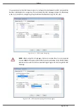
The second part of the DF1 Slave mode is to configure the link between a DF1 node and File
Number combination to a Logix tag. This will allow the DF1 message initiator to effectively
write to, or read from, a Logix tag using traditional File Numbers (e.g. N7, F8, etc.).
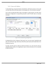
Figure 3.19. – DF1 Slave Mapping
NOTE: When using PLC-2 messages, there are no data files. You are required
to enter PLC2 in the space of the data file as shown below. Only the DF1 Node
address will be used to link the selected Target Tag to the incoming PLC2 DF1
message.
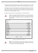
Figure 3.20 – DF1 Slave Mapping (PLC2 Messages)
Summary of Contents for PLX51-DF1-MSG
Page 1: ...PLX51 DF1 MSG DF1 Messenger DF1 to EtherNet IPTM Messenger December 2017 USER MANUAL...
Page 4: ...Page 4 of 69...
Page 10: ...Page 10 of 69...
Page 48: ...Operation Page 48 of 69...
Page 60: ...Page 60 of 69...
Page 64: ...Page 64 of 69...
Page 68: ...Page 68 of 69...

