MVI69L-MBS ♦ Platform
Reference
Modbus Serial Lite Communication Module
User Manual
ProSoft Technology, Inc.
Page 117 of 130
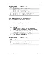
Block 9956: Request from Module to Processor
Offset
Description
0
Read Block ID: 9956
1
Write Block ID: 9956
2
Number of word registers in Modbus data set
3
Starting address for Modbus data set
4 to 239
Data
The ladder logic is responsible for parsing and copying the received message
and performing the proper control operation as expected by the Master device.
The processor must then respond to the Pass-Through control block with an
output image write block with the following format.
This informs the module that the command has been processed and can be
cleared from the Pass-Through queue.
Block 9956: Response from Processor to Module
Offset
Description
0
Write Block ID: 9956
1 to 239
Spare
7.4.14 Pass-through Formatted Block for Functions 6 and 16 with
Float Data Block (9957)
Block 9957: Pass-Through Formatted Block for Functions 6 and 16 with Float
Data Block
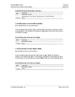
Block 9957: Request from Module to Processor
Offset
Description
0
Read Block ID: 9957
1
Write Block ID: 9957
2
Number of word registers in Modbus data set
3
Starting address for Modbus data set
4 to 239
Data
The ladder logic is responsible for parsing and copying the received message
and performing the proper control operation as expected by the Master device.
The processor must then respond to the Pass-Through block with a write block
with the following format.


