background image

Installing and Configuring the Module 

MVI56-DEM 

 ControlLogix Platform 


Honeywell DE Communication Module 


ProSoft Technology, Inc. 

Page 19 of 80 

March 6, 2008 
 

Fill in the dialog box as shown adjusting the Name, Description and Slot options 
for your application. You must select the 

Comm Format

 as 

Data - INT

 in the 

dialog box. Failure to set the 

Assembly Instance

 and 

Size

 values correctly will 

result in a module that will not communicate over the backplane of the 
ControlLogix rack. Click Next to display the following dialog box. 


Select the Request Packet Interval value for scanning the I/O on the module. 
This value represents the minimum frequency that the module will handle 
scheduled events. This value should not be set to less than 1 millisecond. Values 
between 1 and 10 milliseconds should work with most applications. 

After completing the module setup, the Controller Organization window displays 
the module's presence. The data required for the module is defined to the 
application, and objects are allocated in the Controller Tags data area. The 
Controller Organization window is shown in the following example: 


Summary of Contents for inRAx MVI56-DEM

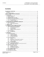
Page 1: ...MVI56 DEM ControlLogix Platform Honeywell DE Communication Module User Manual March 06 2008...

Page 2: ...ithout notice and does not represent a commitment on the part of ProSoft Technology Improvements and or changes in this manual or the product may be made at any time These changes will be made periodi...

Page 3: ...T4 DEMKO 07ATEX0710717X Your Feedback Please We always want you to feel that you made the right decision to use our products If you have suggestions comments compliments or complaints about the produ...

Page 4: ......

Page 5: ...0 4 1 3 Required Software 30 4 1 4 Using the Configuration Debug Port 30 4 1 5 Main Menu 32 4 2 LED Status Indicators 35 4 2 1 Troubleshooting 36 5 REFERENCE 37 5 1 Product Specifications 37 5 1 1 Fea...

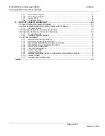
Page 6: ...71 6 4 Procedures for Return of Units Out of Warranty 72 6 4 1 Un repairable Units 72 6 4 2 Purchasing Warranty Extension 73 6 5 LIMITED WARRANTY 73 6 5 1 What Is Covered By This Warranty 73 6 5 2 Wh...

Page 7: ...c and Troubleshooting Verifying Communication page 35 Diagnostics and Troubleshooting page 29 This section describes how to verify communications with the network Diagnostic and Troubleshooting proced...

Page 8: ...MVI56 DEM ControlLogix Platform Start Here Honeywell DE Communication Module Page 8 of 80 ProSoft Technology Inc March 6 2008...

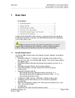
Page 9: ...ccessful installation 1 1 System Requirements The MVI56 DEM module requires the following minimum hardware and software components Rockwell Automation processor with compatible power supply and one fr...

Page 10: ...gix processor and power supply please do so before installing the MVI56 DEM module Refer to your Rockwell Automation product documentation for installation instructions Warning You must follow all saf...

Page 11: ...ing holes of the rack 5 Make a note of the slot location You will need to identify the slot in which the module is installed in order for the sample program to work correctly Slot numbers are identifi...

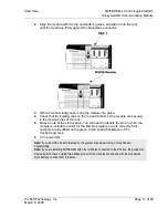
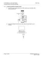
Page 12: ...le Page 12 of 80 ProSoft Technology Inc March 6 2008 1 4 Connect your PC to the Processor 1 Connect the right angle connector end of the cable to your controller at the communications port 2 Connect t...

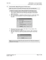
Page 13: ...menu and then choose Download RSLogix will establish communication with the processor 2 When communication is established RSLogix will open a confirmation dialog box Click the Download button to trans...

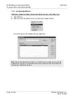
Page 14: ...n with the processor follow these steps 1 Open RSLinx 2 Open the Communications menu and choose Configure Drivers This action opens the Configure Drivers dialog box Note If the list of configured driv...

Page 15: ...e fails verify that the cables are connected correctly between the processor and the serial port on your computer and then try again If you are still unable to auto configure the port refer to your RS...

Page 16: ...MVI56 DEM ControlLogix Platform Start Here Honeywell DE Communication Module Page 16 of 80 ProSoft Technology Inc March 6 2008...

Page 17: ...e in offline mode to add the module to a project 2 Modify the example ladder logic to meet the needs of your application and copy the ladder logic to the processor Example ladder logic files are provi...

Page 18: ...figuring the Module Honeywell DE Communication Module Page 18 of 80 ProSoft Technology Inc March 6 2008 This action opens the following dialog box Select the 1756 Module Generic 1756 Module from the l...

Page 19: ...the ControlLogix rack Click Next to display the following dialog box Select the Request Packet Interval value for scanning the I O on the module This value represents the minimum frequency that the mo...

Page 20: ...rom the example ladder logic The Controller Organization window should display the User Defined Data Types shown in the following example The next step in module setup is to define the data tag to be...

Page 21: ...pplication Insert the module in the rack and attach the serial communication cable to the debug configuration port and connect the cable from the module to the FTA and 24 VDC power supply Download the...

Page 22: ...member of this object holds the bits to trigger the upload process This process copies the data read from the specific channel to the write data area This process is valuable for removing data mismat...

Page 23: ...ed as the handshaking byte to indicate the arrival of new data from the module The ch1 and ch2 members are use to hold the computed channel numbers received in a read block These values are used as in...

Page 24: ...ion Module Page 24 of 80 ProSoft Technology Inc March 6 2008 Read Object DEM_Read_ch The DEM_Read_ch object is defined to hold the data received from each DE channel and status data computed by the mo...

Page 25: ...o be written to each DE channel on the module The structure of the object used in the example logic is shown in the following example The upload process can be utilized to initialize this data set for...

Page 26: ...ommunication Module Page 26 of 80 ProSoft Technology Inc March 6 2008 Status Object DEMStat This object stores the product and backplane transfer status data of the module The DEMStat object shown in...

Page 27: ...ladder logic are module data transfer special block handling and status data receipt Additionally a power up handler may be needed to handle the initialization of the module s data and to clear any p...

Page 28: ...MVI56 DEM ControlLogix Platform Ladder Logic Honeywell DE Communication Module Page 28 of 80 ProSoft Technology Inc March 6 2008...

Page 29: ...s data is transferred to the ControlLogix processor continuously The Configuration Debug port provides the following functionality Full view of the channel read and write data View of the module s and...

Page 30: ...unning DOS you must obtain and install a compatible communication program The following table lists communication programs that have been tested by ProSoft Technology DOS ProComm as well as several ot...

Page 31: ...previous menu You can always return from a sub menu to the next higher menu by pressing M on your keyboard The organization of the menu structure is represented in simplified form in the following il...

Page 32: ...r other failures Only use these commands if you are specifically directed to do so by ProSoft Technology Technical Support staff Some of these command keys are not listed on the menu but are active ne...

Page 33: ...atus Data Press S to view status data for the currently selected channel This screen displays errors in interfacing with the DE instrument It also displays mismatch errors Viewing Version Information...

Page 34: ...are designed for advanced debugging and system testing only and can cause the module to stop communicating with the processor or with other devices resulting in potential data loss or other failures...

Page 35: ...is communicating with all channels APP Status Amber Blinking The module is communicating with some of the channels On The module is performing a write operation on the backplane BP ACT Amber Off The...

Page 36: ...Verify that all modules in the rack are configured in the ladder logic Module Errors Problem Description Steps to take BP ACT LED remains off or blinks slowly This indicates that backplane transfer op...

Page 37: ...and many other instruments 5 1 1 Features and Benefits The module supports 16 DE channels allowing both single and or multivariable Honeywell transmitters operating in the DE mode to be directly inte...

Page 38: ...tatus Serial Activity Debug Configuration port CFG CFG Port CFG RJ45 DB 9M with supplied cable RS 232 only Application ports PRT1 PRT2 Full hardware handshaking control providing radio modem and multi...

Page 39: ...cussion explains several concepts that are important for understanding the operation of the MVI56 DEM module DE Channels The MVI56 DEM module has been designed to provide a tightly integrated Communic...

Page 40: ...EM controller Allen Bradley Backplane Transfer circuitry Read Command Write Command DE CPU 2 68HC11 Receiver 9 Receiver 16 Write to DE Instrument Circuitry To FTA then to instruments Isolation Barrier...

Page 41: ...or rollover from Channel 16 to 1 3 The Tag ID must be identical and non blank across all logical channels configured for use by a multivariable device 4 You must perform a Download Command on the phys...

Page 42: ...between the module and the ControlLogix processor across the backplane using the module s input and output images The update frequency of the data is determined by the scan rate defined by the user f...

Page 43: ...function of the block of data transferred The block identification codes used by the module are displayed in the following table Block ID Type Description 0 to 1 Write Block Data transferred from the...

Page 44: ...3 Words Channel x Data 82 Words Channel x 1 Data 82 Words Product and Block Status Data 13 Words Spare 3 Words Read Block ID The first part of the block contains the real time PV and SV values and the...

Page 45: ...l x Data 17 Words Channel x 1 Data 17 Words Channel x 2 Data 17 Words Channel x 3 Data 17 Words Channel x 4 Data 17 Words Channel x 5 Data 17 Words Channel x 6 Data 17 Words Channel x 7 Data 17 Words...

Page 46: ...ocessor has been defined SCAN 3000 A B PLC DE Module Transmitter Read Write Database Write Database Read Database Display Data Write Data Download Function 1 Upload Function 2 User Initiated Down Uplo...

Page 47: ...er follows A detailed listing and description of the data is in the Reference chapter of this manual Type Description Real Time PV Value Last Good Value and NaN value SV Value Last God Value and NaN v...

Page 48: ...module executes the Download Command and returns the completion status in the Device Status word Upon receipt of the completion bit the Download write register should be cleared to prevent continuous...

Page 49: ...omparison purposes Performing an Upload The Upload Function performs the step of moving the data that has been read from the instrument database from the PLC Read database into the PLC Write database...

Page 50: ...ted within 6 seconds 24 PV update cycles the flag will be set Data Base Mismatch If any data base mismatch condition is detected the flag will be set SFC Write Detected If an SFC write to the instrume...

Page 51: ...or the mismatch condition to clear If the mismatch was generated as the result of a Download Command the mismatch will be cleared when the next data base is fully read from the instrument 2 Perform a...

Page 52: ...terminal emulator follow these steps to disable the RSLinx Driver 1 Open RSLinx and go to Communications RSWho 2 Make sure that you are not actively browsing using the driver that you wish to stop The...

Page 53: ...Stop on the side of the window 5 After you have stopped the driver you will see the following 6 Upon seeing this you may now use that com port to connect to the debug port of the module Note You may n...

Page 54: ...y Inc March 6 2008 5 4 DB9 to RJ45 Adaptor Cable 14 5 5 Application Port Connection The MVI56 DEM module has a single high density DB connector to attach the module to a FTA The FTA and connection cab...

Page 55: ...r externally The power cabling setup is as follows 24 VDC 5 5 3 Non Redundant Configurations In a typical Non Redundant configuration a single FTA is connected to a single module The FTA available in...

Page 56: ...ting point format 4 8 11 Channel 2 PV Value Floating point format 6 12 15 Channel 3 PV Value Floating point format 8 16 19 Channel 4 PV Value Floating point format 10 20 23 Channel 5 PV Value Floating...

Page 57: ...1 bit for each channel with 1 timeout 0 normal 68 136 137 N A Module Status 0 All OK 1 DE CPU Init Error 2 DE CPU Reset Error 3 DE Timeout Error 5 FTA Not Connected If Status Codes 1 to 3 are receive...

Page 58: ...5 Second Channel LRV lower range value Float format 153 306 309 in Block URV upper range value Float format 155 310 313 URL upper range limit Float format 157 314 317 Damping Float format 159 318 321...

Page 59: ...ead Block ID Read block identification code 0 to 7 5 7 MVI56 DEM Write Block This section contains the format of the write blocks passed from the processor to the module These blocks have block identi...

Page 60: ...0 PV Number 61 Number of PV s 31 62 69 Tag Name 35 70 73 Third Channel LRV LRV URL Float format 37 74 77 URV URV LRV URL Float format 39 78 81 URL Float format 41 82 85 Damping Float format 43 86 87 C...

Page 61: ...V s 82 164 171 Tag Name 86 172 175 Sixth Channel LRV LRV URL Float format 88 176 179 URV URV LRV URL Float format 90 180 183 URL Float format 92 184 187 Damping Float format 94 188 189 Command Bits 95...

Page 62: ...ed to determine completion 1 Function Passed 0 Function Failed 1 Function Passed Flag to be used in conjunction with Function Done Flag When the Function Command is set to anything besides Imaging PV...

Page 63: ...ocouple Detection is enabled in the transmitter This value may be changed in the instrument by the PLC via the Download Function 0 Detection Not Enabled 1 Detection Enabled 10 Freq 50 A flag indicatin...

Page 64: ...nt or by performing an upload copying the read data base to the write data base If the PLC database is downloaded to the instrument the mismatch condition will not clear until the complete database ha...

Page 65: ...in the instrument by the PLC via the Download Function 0 Detection Not Enabled 1 Detection Enabled 2 Freq 50 A flag indicating if 50 or 60 Hertz filtering is being used in the transmitter This value...

Page 66: ...ated counter Updated by the DE CPU every time the SV variable is received from an instrument Function This value describes the operating mode of the DEM for the DE Channel and the corresponding transm...

Page 67: ...0 0 5 2 0 32 0 70 1 0 3 0 48 1 5 2 0 4 1 0 3 1 3 0 5 2 0 6 3 4 0 6 4 0 12 7 5 0 7 8 0 25 5 10 0 8 16 0 51 1 50 0 9 32 0 102 3 100 0 PV Characterization This parameter defines the algorithm used in the...

Page 68: ...DEM ControlLogix Platform Reference Honeywell DE Communication Module Page 68 of 80 ProSoft Technology Inc March 6 2008 Value Hex Description 15 F SVP 16 10 MTT 17 11 STP 18 12 SLV 19 13 SDU 20 14 Ge...

Page 69: ...o contact us at Internet Web Site http www prosoft technology com support E mail address support prosoft technology com Those of us at ProSoft Technology Inc want to provide the best and quickest supp...

Page 70: ...86 21 64518356 x 8011 86 21 64756957 Fax 4 F No 16 Hongcao Road Shanghai China 200233 China 86 21 64518356 x 8011 zhang prosoft technology com Languages spoken include Chinese English Europe Middle Ea...

Page 71: ...thout an RMA number will be returned to the Customer freight collect Contact ProSoft Technical Support for further information 4 Out of warranty returns are not allowed on RadioLinx accessories such a...

Page 72: ...n immediate exchange a new module may be purchased and sent to Customer while repair work is being performed Credit for purchase of the new module will be issued when the new module is returned in acc...

Page 73: ...bject of the sale will 1 conform to and perform in accordance with published specifications prepared approved and issued by ProSoft and 2 will be free from defects in material or workmanship provided...

Page 74: ...nty also does not cover the failure of the Product to perform specified functions or any other non conformance defects losses or damages caused by or attributable to any of the following i shipping ii...

Page 75: ...IMITED TO THE IMPLIED WARRANTIES OF MERCHANTABILITY AND FITNESS FOR A PARTICULAR PURPOSE 6 5 5 LIMITATION OF REMEDIES IN NO EVENT WILL PROSOFT OR ITS DEALER BE LIABLE FOR ANY SPECIAL INCIDENTAL OR CON...

Page 76: ...or other intellectual property in any manner or for any purpose not expressly permitted by any license agreement accompanying such software or other intellectual property E Customer agrees that it sh...

Page 77: ...aws of the State of California without reference to its conflicts of law provisions If for any reason a court of competent jurisdiction finds any provisions of this Warranty or a portion thereof to be...

Page 78: ...MVI56 DEM ControlLogix Platform Support Service Warranty Honeywell DE Communication Module Page 78 of 80 ProSoft Technology Inc March 6 2008...

Page 79: ...Download the Sample Program to the Processor 13 E Exiting the Program 34 F Features and Benefits 37 FTA Not Present 50 Function 66 Functional Overview 7 39 Functional Specifications 39 G General Conc...

Page 80: ...a Channel 32 Sensor Type 67 SFC Write Detected 50 Special DB byte 64 Start Here 7 9 Status Bits 1 to 3 65 Status Object DEMStat 26 Support Service Warranty 7 69 SV updated counter 66 System Requireme...

Reviews: