MVI56-DEM
♦
ControlLogix Platform
Reference
Honeywell DE Communication Module
Page 58 of 80
ProSoft Technology, Inc.
March 6, 2008
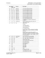
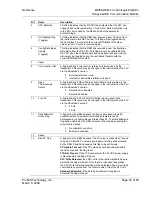
Words Bytes
Channel
Description
Start
Stop
86
172
PV update counter
173
SV update counter
87 174
Spare
175
Function
88
176
DE CFG: Operational Mode
177
Damping
89 178
PV
Characterization
179
Sensor
Type
90 180
PV
Number
181
Number of PV's
91 182
189
Tag
Name
95 190
197
Serial
Number
99 198
205
Software
Revision
103 206 237
Scratch
Pad
119 238 301
Transmitter
Status
151
302 305
Second Channel
LRV: lower range value (Float format)
153
306 309
in Block
URV: upper range value (Float format)
155
310 313
URL: upper range limit (Float format)
157
314 317
Damping (Float format)
159
318 321
LRL: lower range limit (Float format)
161
322 323
Device Status Flags 1
162
324 325
Device Status Flags 2
163
326
Special DB Byte
327
Status Bits 1
164
328
Status Bits 2
329
Status Bits 3
165 330 331
Spare
166
332 333
PV Value 0 to 16383
167
334
Cfg Database update counter
335
Communication error counter
168
336
PV update counter
337
SV update counter
169 338
Spare
339
Function
170
340
DE CFG: Operational Mode
341
Damping
171 342
PV
Characterization
343
Sensor
Type
172 344
PV
Number
345
Number of PV's

