background image

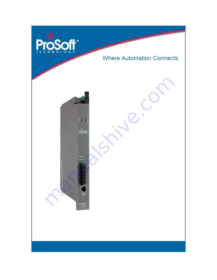
MVI71-HART 

PLC Platform 

HART Multi-drop Master 
Communication Module 


October 7, 2020   

USER MANUAL 

Summary of Contents for MVI71-HART

Page 1: ...MVI71 HART PLC Platform HART Multi drop Master Communication Module October 7 2020 USER MANUAL...

Page 2: ...x inRAx ProTalk and RadioLinx are Registered Trademarks of ProSoft Technology Inc All other brand or product names are or may be trademarks of and are used to identify products and services of their r...

Page 3: ...CONNECTER L QUIPEMENT COUPER LE COURANT OU S ASSURER QUE L EMPLACEMENT EST D SIGN NON DANGEREUX Warnings North America Warnings A Warning Explosion Hazard Substitution of components may impair suitab...

Page 4: ...echargeable Lithium Vanadium Pentoxide battery to backup the real time clock and CMOS The battery should last for the life of the module The module must be powered for approximately twenty hours befor...

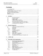
Page 5: ...Module Configuration 15 2 1 Installing and Configuring the Module 16 2 2 Module Data 17 2 2 1 Status Data 17 2 2 2 User Data 17 2 2 3 Command Control Data 17 2 3 Configuration File 18 2 3 1 MODULE 19...

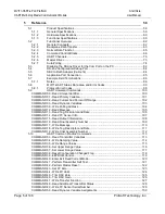
Page 6: ...Percent Of Range 102 COMMAND 03 Read Dynamic Variables 103 COMMAND 06 Write Polling Address 104 COMMAND 12 Read Message 105 COMMAND 13 Read Tag Descriptor and Date 106 COMMAND 14 Read PV Sensor Info 1...

Page 7: ...Information 134 COMMAND 55 Write Transmitter Variable Damping Value 135 COMMAND 56 Write Transmitter Variable Sensor Serial Number 136 COMMAND 57 Read Unit Tag Descriptor Date 137 COMMAND 58 Write Uni...

Page 8: ...rce and to the MVI71 HART module s application port s 1 1 System Requirements The MVI71 HART module requires the following minimum hardware and software components Rockwell Automation PLC processor wi...

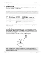
Page 9: ...Port 1 Cable Cable 14 RJ45 to DB9 Male Adapter cable For DB9 Connection to Module s Port If any of these components are missing please contact ProSoft Technology Support for replacement parts 1 3 Set...

Page 10: ...g the device After you have checked the placement of the jumpers insert MVI71 HART into the PLC chassis Use the same technique recommended by Rockwell Automation to remove and install PLC modules Warn...

Page 11: ...ule User Manual Page 11 of 146 ProSoft Technology Inc 1 5 Connect your PC to the Processor 1 Connect the right angle connector end of the cable to your controller at the communications port 2 Connect...

Page 12: ...e key switch on the front of the PLC processor must be in the REM position 1 If you are not already online to the processor open the Communications menu and then choose Download RSLogix will establish...

Page 13: ...processor from Program mode to Run mode Note If you receive an error message during these steps refer to your RSLogix documentation to interpret and correct the error 1 6 1 Configuring the RSLinx Driv...

Page 14: ...Configuration Successful click the OK button to dismiss the dialog box Note If the auto configuration procedure fails verify that the cables are connected correctly between the processor and the seri...

Page 15: ...ology Inc 2 Module Configuration In This Chapter Installing and Configuring the Module 16 Module Data 17 Configuration File 18 This section contains the setup procedure data and ladder logic for succe...

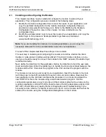
Page 16: ...p in installing and configuring the module is to define whether the block transfer or side connect interface will be utilized If the block transfer interface is to be used you should be ready to conne...

Page 17: ...the data areas in the module s database is determined by the parameters set in the configuration file You must transfer floating point values to float files When the block transfer interface is used l...

Page 18: ...be identified by the program If the module is not considering a parameter look at the label for the data item Each parameter s value is separated from the label with the character This character is u...

Page 19: ...mber of registers to accept from the processor Error Status Offset 1 or 0 to 3935 This parameter defines the database location where the module status data will be stored If set to 1 data not placed i...

Page 20: ...determines if the specific HART channel will emulate a primary or secondary master You can have only one of each type on a HART network If you plan on using a handheld device secondary master you mus...

Page 21: ...poll command so the user should configure this value considering one command for the auto poll For example if the user configures two commands the command count parameter should be set as 3 This param...

Page 22: ...3 Bytes The bytes in each word are swapped 1234 2143 Depending on the host processor using the data the proper swap code must be utilized to present the data in the correct format Max Device Count 1 t...

Page 23: ...command list is processed from top Command 0 to bottom Command 99 then the process is repeated A poll interval parameter is associated with each command to specify a minimum delay time in seconds betw...

Page 24: ...ables 06 Write Polling Address 07 Read Loop Configuration 08 Read Dynamic Variable Classifications 09 Read Device Variables with Status 11 Read Unique Identifier Associated With Tag 12 Read Message 13...

Page 25: ...ber Of Response Preambles 60 Read Analog Channel and Percent of Range 61 Read Dynamic Variables and PV Analog Ch 62 Read Analog Channels 63 Read Analog Channel Information 64 Write Analog Channel Addi...

Page 26: ...f HART devices on startup 4 Places the command in enabled mode This option is valid only if there is a specified Enabled DB Address see below If the Virtual Database word specified in Enabled DB Addre...

Page 27: ...ssociated operations Swap Code Description 0 None No Change is made in the byte ordering 1234 1234 1 Words The words are swapped 1234 3412 2 Words Bytes The words are swapped then the bytes in each wo...

Page 28: ...4 4321 3 Bytes The bytes in each word are swapped 1234 2143 Use Long 0 or 1 This parameter defines if the command will be executed with short or long address If the value is 0 then the configured comm...

Page 29: ...yte ordering 1234 1234 1 Words The words are swapped 1234 3412 2 Words Bytes The words are swapped then the bytes in each word are swapped 1234 4321 3 Bytes The bytes in each word are swapped 1234 214...

Page 30: ...he following integer data Word High Byte Low Byte 0 Status Word 1 Primary Variable Units Code Second Variable Units Code 2 Third Variable Units Code Fourth Variable Units Code So this command will ret...

Page 31: ...Write Address 1 This parameter is ignored since no data is sent to the HART device this is a read command 15 DB Swap Code 3 This parameter is ignored since no data is sent to the HART device this is...

Page 32: ...ress Damping Value Floating Point Read from slave to MVI 2 240 word address Status Word Integer Read from slave to MVI 1 290 word address The user can configure the command parameters as described in...

Page 33: ...pped with a pre loaded configuration file In order to edit this file you may transfer the file from the module to your PC After editing you must transfer the file back to the module for your changes t...

Page 34: ...ication program The following table lists communication programs that have been tested by ProSoft Technology DOS ProComm as well as several other terminal emulation programs Windows 3 1 Terminal Windo...

Page 35: ...ation file should be stored and select Zmodem as the receiving protocol When you have completed your selections click Close 4 Press S Send Module Configuration and then press Y to confirm the transfer...

Page 36: ...tion Module User Manual Page 36 of 146 ProSoft Technology Inc The configuration file is now on your PC at the location you specified 5 You can now open and edit the file in a text editor such as Windo...

Page 37: ...steps to transfer a configuration file from your PC to the module 1 Connect your PC to the Configuration Debug port of the module using a terminal program such as HyperTerminal Press to display the m...

Page 38: ...HyperTerminal select Send File The Send File dialog appears 5 Use the Browse button to locate the configuration file your computer Note This procedure assumes that you are transferring a newly edited...

Page 39: ...end dialog box When the transfer is complete the screen indicates that the module has reloaded program values and displays information about the module 8 Your module now contains the new configuration...

Page 40: ...e handled by the ladder logic are module data transfer special block handling and status data receipt Additionally a power up handler may be needed to handle the initialization of the module s data an...

Page 41: ...nformation on diagnostics and troubleshooting in the following forms LED status indicators on the front of the module provide general information on the module s status Status data contained in the mo...

Page 42: ...top of the tree and one or more sub menus for each menu command The first menu you see when you connect to the module is the Main menu Because this is a text based menu system you enter commands by ty...

Page 43: ...he screen they perform different actions on the module and may not be used interchangeably 4 1 2 Required Software In order to send and receive data over the serial port COM port on your computer to t...

Page 44: ...settings for baud rate parity and handshaking 4 On computers with more than one serial port verify that your communication program is connected to the same port that is connected to the module If you...

Page 45: ...is command to display the current configuration and statistics for the module Opening the Database View Menu Press D to open the Database View menu Use this menu command to view the current contents o...

Page 46: ...sked to provide this information when calling for technical support on the product Values at the bottom of the display are important in determining module operation The Program Scan Counter value is i...

Page 47: ...e main menu This action will allow the module to resume its normal high speed operating mode Viewing the Slave Status List Press V to view the slave status values associated with the ports The slave s...

Page 48: ...t the beginning of a HART message Retry Count Increments every time a HART command fails and is retried Check Byte Increments when a Checksum error is detected in the received HART packet Overrun Pari...

Page 49: ...s limited without a thorough understanding of the protocol Important When in analyzer mode program execution will slow down Only use this tool during a trouble shooting session Before disconnecting fr...

Page 50: ...1 milliseconds ticks 6 5 milliseconds ticks 7 10 milliseconds ticks 8 50 milliseconds ticks 9 100 milliseconds ticks 0 Turn off timing marks Removing Timing Marks in the Data Analyzer Press 0 to turn...

Page 51: ...s driven high on the port R These characters are inserted when the RTS line is dropped low on the port CS These characters are displayed when the CTS line is recognized high _TT_ These characters are...

Page 52: ...ations HEX is the best format to view the data and this does include ASCII based messages because some characters will not display on HyperTerminal and by capturing the data in HEX we can figure out w...

Page 53: ...ug port of the module After you have pressed B you should see something like the following The R means that the module is transitioning the communications line to a transmit state All characters shown...

Page 54: ...page of data Redisplays last selected page of data Redisplays refreshes this menu Goes up one level to main menu Protocol Menu M Main Menu Redisplaying the Current Page Press S to display the current...

Page 55: ...ck one page of data Redisplays last selected page of data Redisplays refreshes this menu Goes up one level to main menu Protocol Menu M Main Menu Redisplaying the Current Page Press S to display the c...

Page 56: ...Green On Data is being transferred between the module s HART channel 3 and a remote terminal Off No data is being transferred on the port CH4 Green On Data is being transferred between the module s H...

Page 57: ...logic Processor I O LED flashes This indicates a problem with backplane communications A problem could exist between the processor and any installed I O module not just the MVI71 HART Verify that all...

Page 58: ...apter Product Specifications 59 Functional Overview 62 Disabling the RSLinx Driver for the Com Port on the PC 82 RS 232 Configuration Debug Port 84 DB9 to RJ45 Adaptor Cable 14 84 Application Port Con...

Page 59: ...mands to interface with slave devices on their own networks Each port is individually configurable Data is exchanged between the HART network and the PLC processor backplane using the internal databas...

Page 60: ...ntation of the protocol Following are some general specifications for the module Built in accordance to the HART Bell 202 Frequency Shift Keying FSK standard to superimpose digital signals at a low le...

Page 61: ...T Network Communications Supports four master channels Each channel on the module is configured independently to emulate a HART master Burst mode can be used for faster update of data from a slave dev...

Page 62: ...ports 4 Set up the communication interface for the debug configuration port After the module has received the configuration the module begins receiving and transmitting messages with devices on the s...

Page 63: ...he data transfer method used to move data between the PLC processor the MVI71 HART module and the serial network HART Port Driver Master Driver Master Driver Module s Internal Database MVI71 HART Modu...

Page 64: ...PLC Block contains no data These block identification codes can be broken down into two groups Normal data transfer blocks 1 to 67 and Command control blocks 9902 to 9999 Each of these groups of block...

Page 65: ...and the ladder logic required The following topics discuss the structure and function of each block Read Block These blocks of data transfer information from the module to the PLC processor The struc...

Page 66: ...valid data If the word contains a value from 1 to 20 the data contained in the block should be placed in the appropriate position of the module s database Under normal conditions the value used for t...

Page 67: ...for this command block is shown in the following table Word Offset in Block Data Field s Description 0 Block ID This field contains the value of 9902 identifying the enable command to the module 1 Por...

Page 68: ...not defined the command will not be placed in the command queue Normal processing of the command list will continue after the commands specified in this block are processed Command List Error Status...

Page 69: ...ll have a value of 1 to MaxCommands 1 5 to 54 Command List Errors Each word of this area contains the last error value recorded for the command The command index of the first value offset 4 is specifi...

Page 70: ...ation CHANNEL 1 HART Port 0 CHANNEL 2 HART Port 1 CHANNEL 3 HART Port 2 CHANNEL 4 HART Port 3 The HART protocol uses the Bell 202 standard frequency shift keying FSK signal to communicate at 1200 baud...

Page 71: ...k address 1 to 15 The user may configure the maximum slave addresses to be polled Refer to the Auto Polling section for more information about auto poll mode User configured commands can be issued on...

Page 72: ...ed slaves in the network address 1 to 15 Refer to the Auto Polling section for more information about auto poll mode User configured commands can be issued on each channel to the HART devices Up to 99...

Page 73: ...6 1 2 1 The master driver is configured as specified by the HART CFG file 2 The master will construct control commands using the data in the database 3 The master will send these commands and read re...

Page 74: ...the command The parameters in the command will be used to store the data received from the bursting slave There can only be one slave bursting on the network at any one time This mode can be used for...

Page 75: ...te Hardware Revision Level Physical Signaling Code 1 CMD 0 Info 10 byte Device Flags 1 CMD 0 Info 11 to 13 byte Device ID 3 CMD 0 Long Address 14 byte Minimum number of preambles to be sent with the r...

Page 76: ...D 14 Cfg 80 to 83 float Lower transducer limit 4 CMD 14 Cfg 84 to 87 float Minimum span 4 CMD 14 Cfg 88 to 91 float PV upper range value 4 CMD 15 Cfg 92 to 95 float PV lower range value 4 CMD 15 Cfg 9...

Page 77: ...RT device address is 0 you must configure the channel for Point to Point mode In point to point mode the module only polls for a single instrument with a polling address of zero When the instrument is...

Page 78: ...rence HART Multi drop Master Communication Module User Manual Page 78 of 146 ProSoft Technology Inc When the point to point mode of auto polling is enabled Auto Poll Code P the following diagram appli...

Page 79: ...to be polled in multi drop mode For example if the MAX DEVICE COUNT parameter is set to 3 the channel will poll for polling addresses 1 2 and 3 It is important when assigning the device polling addres...

Page 80: ...nd 3 After a certain number of iterations the HART Driver will ready the configuration data for the next device if there is one Each time configuration information is acquired it will be for a differe...

Page 81: ...HART PORT 0 Auto Poll DB Address 400 Max Device Count 15 DB Address Status 3661 HART PORT 1 Auto Poll DB Address 1200 Max Device Count 15 DB Address Status 3662 HART PORT 2 Auto Poll DB Address 2000...

Page 82: ...r follow these steps to disable the RSLinx driver 1 Open RSLinx and go to COMMUNICATIONS RSWHO 2 Make sure that you are not actively browsing using the driver that you wish to stop The following shows...

Page 83: ...on on the side of the window 5 After you have stopped the driver you will see the following 6 You may now use the com port to connect to the debug port of the module Note You may need to shut down and...

Page 84: ...g Port This port is physically an RJ45 connection An RJ45 to DB 9 adapter cable is included with the module This port permits a PC based terminal emulation program to view configuration and status dat...

Page 85: ...er Manual Page 85 of 146 ProSoft Technology Inc 5 6 Application Port Connection The MVI71 HART module has a single terminal connector to attach the module to the HART networks Refer to Example Field T...

Page 86: ...You can mix Loop powered and Self powered instruments on the same unit However you cannot mix Loop powered and Self powered instruments on the same channel 2 For Master Powered Multi drop Mode and Poi...

Page 87: ...User Manual Page 87 of 146 ProSoft Technology Inc 5 For multi drop applications the 1K resistor should be normally used when one transmitter is connected to the port If you increase the number of devi...

Page 88: ...MVI71 HART PLC Platform Reference HART Multi drop Master Communication Module User Manual Page 88 of 146 ProSoft Technology Inc...

Page 89: ...MVI71 HART PLC Platform Reference HART Multi drop Master Communication Module User Manual Page 89 of 146 ProSoft Technology Inc...

Page 90: ...MVI71 HART PLC Platform Reference HART Multi drop Master Communication Module User Manual Page 90 of 146 ProSoft Technology Inc...

Page 91: ...MVI71 HART PLC Platform Reference HART Multi drop Master Communication Module User Manual Page 91 of 146 ProSoft Technology Inc...

Page 92: ...MVI71 HART PLC Platform Reference HART Multi drop Master Communication Module User Manual Page 92 of 146 ProSoft Technology Inc...

Page 93: ...blocks transferred from the module to the processor 10 Write Block Count This field contains the total number of write blocks transferred from the processor to the module 11 Parse Block Count This fi...

Page 94: ...24 Channel 1 Current Error Code Current error code for Channel 25 Channel 1 Last Error Code Last error code reported for Channel 26 Channel 2 State Channel 2 state machine value used for debugging 0...

Page 95: ...for slave address 1 Bit 0 is not used If the bit is set the slave is in error If the bit is clear 0 the slave is not in error 40 Channel 3 Device Poll List bit mapped Each bit in this word corresponds...

Page 96: ...n this word corresponds to a slave address on the network starting at bit 1 for slave address 1 Bit 0 is not used If the bit is set the slave uses the long address If the bit is clear 0 the slave does...

Page 97: ...error code is the first word of the Integer Data Block returned from every HART command executed This word has information about the execution of the command by the HART device Refer to the following...

Page 98: ...Error BIT 4 Framing Error BIT 3 Checksum Error BIT 2 Reserved BIT 1 RX Buffer Overflow BIT 0 Undefined SECOND BYTE BIT 0 to BIT 7 All 0 BIT 7 OF FIRST BYTE 0 COMMAND ERROR FIRST BYTE Bits 6 to 0 not...

Page 99: ...ts Command Specific Errors 8 Update Failed Update In Progress Set to Nearest Possible Value 9 Applied Process Too High Lower Range Value Too High Not in Fixed Current Mode 10 Applied Process Too Low L...

Page 100: ...on like Manufacturer ID Device Type Code Software Revision Hardware Revision and so on Write Parameters NONE Floating Point Data Returned NONE Integer Data Returned Word High Byte Low Byte 0 STATUS WO...

Page 101: ...gy Inc COMMAND 01 Read Primary Variable Description This command gets the device Primary Variable and the Primary Variable Units Write Parameters NONE Floating Point Data Returned Word High Byte Low B...

Page 102: ...02 Read Current And Percent Of Range Description This command gets the current of the loop that is forced by the HART device and the Percent of Range of the Current Write Parameters NONE Floating Poi...

Page 103: ...the current and four predefined dynamic Variables Write Parameters NONE Floating Point Data Returned Word High Byte Low Byte 0 Current mA 1 2 Primary Variable 3 4 Second Variable 5 6 Third Variable 7...

Page 104: ...scription This command sets the polling address of a HART device Extreme care should be taken when you use this command because you can loose the communication with the device Write Parameters Word Hi...

Page 105: ...ined in the HART Device and written by the Write Message command 17 Write Parameters NONE Floating Point Data Returned NONE Integer Data Returned Word High Byte Low Byte 0 STATUS WORD 1 Message ASCII...

Page 106: ...the last Date it has been configured Write Parameters NONE Floating Point Data Returned NONE Integer Data Returned Word High Byte Low Byte 0 STATUS WORD 1 TAG ASCII Character 0 TAG ASCII Character 1...

Page 107: ...d gets information about the Primary Variable sensor like limits and span Write Parameters NONE Floating Point Data Returned Word High Byte Low Byte 0 Upper Sensor Limit 1 2 Lower Sensor Limit 3 4 Min...

Page 108: ...information about the Primary Variable Output Information Write Parameters NONE Floating Point Data Returned Word High Byte Low Byte 0 Upper Range Value 1 2 Lower Range Value 3 4 Damping Value Sec 5...

Page 109: ...nology Inc COMMAND 16 Read Final Assembly Number Description This command reads the final assembly number of the HART device Write Parameters NONE Floating Point Data Returned NONE Integer Data Return...

Page 110: ...SCII message contained in the HART Device and that can be read with command 12 Write Parameters Word High Byte Low Byte 0 Packed ASCII Message Byte 0 Packed ASCII Message Byte 1 1 Packed ASCII Message...

Page 111: ...ed ASCII TAG Byte 3 2 Packed ASCII TAG Byte 4 Packed ASCII TAG Byte 5 3 Packed ASCII Descriptor Byte 0 Packed ASCII Descriptor Byte 1 8 Packed ASCII Descriptor Byte 10 Packed ASCII Descriptor Byte 11...

Page 112: ...This command writes the final assembly number of the HART device Write Parameters Word High Byte Low Byte 0 Final Assembly Number 0 Final Assembly Number 1 1 Final Assembly Number 2 Final Assembly Nu...

Page 113: ...For Slot 1 1 Transmitter Variable Code For Slot 2 Transmitter Variable Code For Slot 3 Floating Point Data Returned Word High Byte Low Byte 0 Variable for Slot 0 1 2 Variable for Slot 0 3 4 Variable f...

Page 114: ...c COMMAND 34 Write Damping Value Description This command writes the damping value of a HART device Write Parameters Word High Byte Low Byte 0 Floating Point Damping Value Sec 1 Floating Point Data Re...

Page 115: ...ange Value Byte 0 1 Floating Point Upper Range Value Byte 1 Floating Point Upper Range Value Byte 2 2 Floating Point Upper Range Value Byte 3 Floating Point Lower Range Value Byte 0 3 Floating Point L...

Page 116: ...roSoft Technology Inc COMMAND 36 Set Upper Range Value Description This command is similar in effect to push the SPAN button of the HART device but doing it remotely through the HART network Write Par...

Page 117: ...roSoft Technology Inc COMMAND 37 Set Lower Range Value Description This command is similar in effect to push the ZERO button of the HART device but doing it remotely through the HART network Write Par...

Page 118: ...e 118 of 146 ProSoft Technology Inc COMMAND 38 Reset Configuration Changed Flag Description This command resets the status bit that indicates that configuration has been changed Write Parameters NONE...

Page 119: ...Technology Inc COMMAND 39 EEPROM Control Description This command operates over the EEPROM changing its settings Write Parameters Word High Byte Low Byte 0 EEPROM Control Code EEPROM Control Code Floa...

Page 120: ...Inc COMMAND 40 Enter Exit Fixed Current Mode Description This command writes the damping value of a HART device Write Parameters Word High Byte Low Byte 0 Floating Point Current mA 1 Floating Point Da...

Page 121: ...f 146 ProSoft Technology Inc COMMAND 41 Perform Transmitter Self Test Description This command starts the HART device Self Test to find if there is any problem with the device hardware Write Parameter...

Page 122: ...odule User Manual Page 122 of 146 ProSoft Technology Inc COMMAND 42 Perform Master Reset Description This command performs a master reset in the HART device Write Parameters NONE Floating Point Data R...

Page 123: ...ication Module User Manual Page 123 of 146 ProSoft Technology Inc COMMAND 43 Set PV Zero Description This command forces the Primary Value to Zero Write Parameters NONE Floating Point Data Returned NO...

Page 124: ...c COMMAND 44 Write PV Units Description This command changes the setting of the Primary Variable units Write Parameters Word High Byte Low Byte 0 Primary Variable Units Code Primary Variable Units Cod...

Page 125: ...This command calibrates the device Digital to analog converter zero This is done by writing the same current value that is measured in the loop Write Parameters Word High Byte Low Byte 0 Floating Poin...

Page 126: ...This command calibrates the device Digital to analog converter gain This is done by writing the same current value that is measured in the loop Write Parameters Word High Byte Low Byte 0 Floating Poin...

Page 127: ...MMAND 47 Write Transfer Function Description This command changes the setting of the Transfer Function of the HART device Write Parameters Word High Byte Low Byte 0 Transfer Function Code Transfer Fun...

Page 128: ...ption This command gets extended information about the status of the Transmitter This information is specific for each transmitter Write Parameters NONE Floating Point Data Returned NONE Integer Data...

Page 129: ...hanges the sensor serial number of the Primary Variable Write Parameters Word High Byte Low Byte 0 Sensor Serial Number Byte 0 Sensor Serial Number Byte 1 1 Sensor Serial Number Byte 2 Sensor Serial N...

Page 130: ...s command gets the actual assignment of the Dynamic Variables returned with command 3 Write Parameters NONE Floating Point Data Returned NONE Integer Data Returned Word High Byte Low Byte 0 STATUS WOR...

Page 131: ...High Byte Low Byte 0 Transmitter Variable Code For Primary Variable Transmitter Variable Code For Second Variable 1 Transmitter Variable Code For Third Variable Transmitter Variable Code For Fourth V...

Page 132: ...MMAND 52 Set Transmitter Variable Zero Description This command forces a selected transmitter variable to zero Write Parameters Word High Byte Low Byte 0 Transmitter Variable Code Transmitter Variable...

Page 133: ...smitter Variable Units Description This command changes a selected transmitter variable unit Write Parameters Word High Byte Low Byte 0 Transmitter Variable Code Transmitter Variable Units Code Floati...

Page 134: ...e sensor Write Parameters Word High Byte Low Byte 0 Transmitter Variable Code Transmitter Variable Code Floating Point Data Returned Word High Byte Low Byte 0 Transmitter Variable Upper Limit 1 2 Tran...

Page 135: ...le Write Parameters Word High Byte Low Byte 0 Transmitter Variable Code Transmitter Variable Damping Value Byte 0 1 Transmitter Variable Damping Value Byte 1 Transmitter Variable Damping Value Byte 2...

Page 136: ...Parameters Word High Byte Low Byte 0 Transmitter Variable Code Transmitter Variable Sensor Serial Number Byte 0 1 Transmitter Variable Sensor Serial Number Byte 1 Transmitter Variable Sensor Serial N...

Page 137: ...d the last Date it has been configured Write Parameters NONE Floating Point Data Returned NONE Integer Data Returned Word High Byte Low Byte 0 STATUS WORD 1 TAG ASCII Character 0 TAG ASCII Character 1...

Page 138: ...ed ASCII TAG Byte 3 2 Packed ASCII TAG Byte 4 Packed ASCII TAG Byte 5 3 Packed ASCII Descriptor Byte 0 Packed ASCII Descriptor Byte 1 8 Packed ASCII Descriptor Byte 10 Packed ASCII Descriptor Byte 11...

Page 139: ...Response Preambles Description This command sets the number of preambles that the HART slave will use in every command response Write Parameters Word High Byte Low Byte 0 Number of Response Preambles...

Page 140: ...rite Burst Mode Command Number Description This command sets the command number that the HART device will use in Burst Mode Write Parameters Word High Byte Low Byte 0 Burst Mode Command Number Burst M...

Page 141: ...logy Inc COMMAND 109 Burst Mode Control Description This command sets the HART device Burst Mode Write Parameters Word High Byte Low Byte 0 Burst Mode Control Code Burst Mode Control Code Floating Poi...

Page 142: ...iption This command gets all dynamic Variables Write Parameters NONE Floating Point Data Returned Word High Byte Low Byte 0 Primary Variable 1 2 Second Variable 3 4 Third Variable 5 6 Fourth Variable...

Page 143: ...t down issues North America Corporate Location Europe Middle East Africa Regional Office Phone 1 661 716 5100 info prosoft technology com Languages spoken English Spanish REGIONAL TECH SUPPORT support...

Page 144: ...EEPROM Control 119 COMMAND 40 Enter Exit Fixed Current Mode 120 COMMAND 41 Perform Transmitter Self Test 121 COMMAND 42 Perform Master Reset 122 COMMAND 43 Set PV Zero 123 COMMAND 44 Write PV Units 1...

Page 145: ...ping Through 5 Pages of Commands 54 Multi drop Mode 79 MVI Multi Vendor Interface Modules 3 MVI71 HART Status Data Area and Error Codes 17 66 93 N Navigation 42 Normal Data Transfer 65 Notes 86 O Open...

Page 146: ...iewing Data in ASCII Text Format 50 Viewing Data in Hexadecimal Format 50 Viewing Module Configuration 45 Viewing Port Status and Configuration 48 Viewing the Master Command List Help 47 Viewing the N...

Reviews: