background image

RLX-IFHS ♦ RadioLinx Industrial Wireless 

Contents 

RadioLinx® Industrial Frequency Hopping Serial Radios 

User Manual 


ProSoft Technology, Inc. 

Page 7 of 107 

November 19, 2013 
 

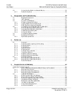
Contents 

Your Feedback Please ........................................................................................................................ 2


How to Contact Us .............................................................................................................................. 2


ProSoft Technology

®

 Product Documentation .................................................................................... 2


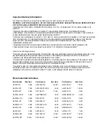
Important Safety Information ............................................................................................................... 3


Recommended Antennas ................................................................................................................... 3


Antenna spacing requirements for user safety ................................................................................... 4


Please Read This Notice .................................................................... 

Error! Bookmark not defined.


EU Requirements ................................................................................................................................ 4


RadioLinx IFH: FCC Part 15 & Industry Canada Rules ...................................................................... 4


RadioLinx IFHS: COMPLIANCE STATEMENT .................................................................................. 4


Agency Approvals & Certifications ...................................................................................................... 5


Agency Approvals & Certifications ...................................................................................................... 5


Guide to the RLX-IFHS User Manual 

11


1


Start Here 

13


1.1


About the RadioLinx Industrial Frequency Hopping Radios ................................... 14


1.1.1


Product Specifications - RLX-IFH9S ....................................................................... 14


1.1.2


Product Specifications - RLX-IFH24S ..................................................................... 16


1.2


Package Contents ................................................................................................... 18


1.3


System Requirements ............................................................................................. 19


1.4


Install ControlScape FH Configuration Software .................................................... 20


1.5


Planning the Network .............................................................................................. 21


1.5.1


Installation Questions .............................................................................................. 22


1.5.2


ProSoft Wireless Designer ...................................................................................... 23


1.6


Configuring the Radios ............................................................................................ 25


1.6.1


Start ControlScape FH ............................................................................................ 25


1.6.2


Set Up the Network ................................................................................................. 26


1.6.3


General Radio Configuration ................................................................................... 31


1.6.4


Set Up the Master Radio ......................................................................................... 32


1.6.5


Add Remote Radios ................................................................................................ 36


1.6.6


Add Repeaters ........................................................................................................ 37


1.6.7


Graphically Define the RF Link ............................................................................... 38


1.6.8


Save the Network Configuration ............................................................................. 40


1.6.9


Transfer the Configuration to the Remote Radios .................................................. 41


1.7


Planning the Physical Installation ............................................................................ 44


1.8


Test the Network Installation Plan ........................................................................... 45


1.9


Verify Communication ............................................................................................. 46


1.9.1


View Operating Network.......................................................................................... 46


1.9.2


Viewing Signal Strength .......................................................................................... 47


1.9.3


Query a Radio Directly ............................................................................................ 48


1.9.4


Query a Radio Remotely ......................................................................................... 49


2


Installing the Radios 

51


2.1


Radio Hardware ...................................................................................................... 52


2.1.1


Radio power requirements ...................................................................................... 52


2.1.2


Connecting antennas .............................................................................................. 53


Summary of Contents for RadioLinx RLX-IFHS

Page 1: ...RLX IFHS RadioLinx Industrial Wireless RadioLinx Industrial Frequency Hopping Serial Radios November 19 2013 USER MANUAL...

Page 2: ...Inc all rights reserved RLX IFHS User Manual November 19 2013 ProSoft Technology ProLinx inRAx ProTalk and RadioLinx are Registered Trademarks of ProSoft Technology Inc All other brand or product nam...

Page 3: ...GAIN OF 24 dB AN ANTENNA HAVING A HIGHER GAIN IS STRICTLY PROHIBITED PER REGULATIONS OF INDUSTRY CANADA THE REQUIRED ANTENNA IMPEDANCE IS 50 OHMS TO REDUCE POTENTIAL RADIO INTERFERENCE TO OTHER USERS...

Page 4: ...range of 2 454 GHz to 2 4835 GHz 3 5 15 GHz to 5 35 GHz is restricted to 200 mW EIRP throughout the European Union RadioLinx IFH FCC Part 15 Industry Canada Rules The statements contained in this Reg...

Page 5: ...id the user s authority to operate the equipment Agency Approvals Certifications Wireless Approvals Visit our web site at www prosoft technology com for current wireless approval information Hazardous...

Page 6: ......

Page 7: ...4 1 1 2 Product Specifications RLX IFH24S 16 1 2 Package Contents 18 1 3 System Requirements 19 1 4 Install ControlScape FH Configuration Software 20 1 5 Planning the Network 21 1 5 1 Installation Que...

Page 8: ...72 4 1 1 Antenna location spacing and mounting 72 4 1 2 Antenna Pattern 73 4 1 3 Antenna Gain 73 4 1 4 Antenna Polarity 74 4 1 5 Whip antennas 74 4 1 6 Collinear array antennas 75 4 1 7 Yagi Array Ant...

Page 9: ...ess Contents RadioLinx Industrial Frequency Hopping Serial Radios User Manual ProSoft Technology Inc Page 9 of 107 November 19 2013 5 2 9 Allocation of Risks 90 5 2 10 Controlling Law and Severability...

Page 10: ...Contents RLX IFHS RadioLinx Industrial Wireless User Manual RadioLinx Industrial Frequency Hopping Serial Radios Page 10 of 107 ProSoft Technology Inc November 19 2013...

Page 11: ...network of RLX IFHS radios Installing the Radios Radio Hardware page 52 Connecting antennas page 53 Connecting Radios to a Device Network page 54 page 54 This section describes how to install the rad...

Page 12: ...Guide to the RLX IFHS User Manual RLX IFHS RadioLinx Industrial Wireless User Manual RadioLinx Industrial Frequency Hopping Serial Radios Page 12 of 107 ProSoft Technology Inc November 19 2013...

Page 13: ...age 13 of 107 November 19 2013 1 Start Here In This Chapter About the RadioLinx Industrial Frequency Hopping Radios 14 Package Contents 18 System Requirements 19 Install ControlScape FH Configuration...

Page 14: ...s a master repeater and remote radio and employs the 128 bit AES encryption algorithm approved by the United States government for top secret information RLX IFH9S radios are quickly and easily config...

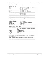
Page 15: ...ts 1 RP SMA connector Weight 1 0 lbs 454 g Environmental Operating Temperature 40 C to 75 C Humidity Up to 100 RH without condensation External Power 10Vdc to 24Vdc Power Consumption 12 W peak Agency...

Page 16: ...er and remote radio and employs the 128 bit AES encryption algorithm approved by the United States government for top secret information RLX IFH24S radios are quickly and easily configured using the i...

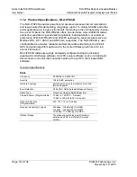
Page 17: ...perature 40 C to 75 C Humidity Up to 100 RH without condensation Vibration IEC 60068 2 6 20g 3 axis Shock IEC 60068 2 27 5g 10Hz to 150Hz External Power 10Vdc to 24Vdc Power Consumption 12 W peak Agen...

Page 18: ...ent Qty Part Name Part Number Part Description 1 RLX IFHS Radio RLX IFHS RadioLinx Industrial Frequency Hopping Serial Radios 1 Cable Cable 15 RS232 For RS232 Connection to the CFG Port 1 Connector 00...

Page 19: ...ns to successfully install and run ControlScape FH Microsoft Windows compatible PC Windows 2000 with Service Pack 2 or higher or Windows XP Professional with Service Pack 2 or higher or Windows 2003 3...

Page 20: ...og box click the Browse button c In the Browse dialog box click My Computer In the list of drives choose the CD ROM drive where you inserted the ProSoft Solutions CD d Select the file prosoft exe and...

Page 21: ...tanks The following illustration shows how a radio network of RLX IFH24S radios could be deployed to connect a variety of PLCs using a variety of industrial protocols You could deploy a similar networ...

Page 22: ...t exposure to weather and provide an adequate stable power source Make sure that your plan complies with the radio s power requirements page 52 and cable specifications Important Radios and antennas m...

Page 23: ...l currently available RadioLinx radios antennas cables connectors and accessories Exports Parts List Site and Link Details and Wizard settings into a variety of common file formats for import into app...

Page 24: ...Windows and Microsoft NET Framework version 2 0 or newer Minimum hardware requirements are 400 MHz or faster Pentium PC 128 MB RAM CD ROM drive 280 MB available hard drive space The Microsoft NET Fram...

Page 25: ...e the Network Configuration page 40 Save the Radio Configuration page 35 1 6 1 Start ControlScape FH You will use an application software program called ControlScape FH to configure the RLX IFHS radio...

Page 26: ...re defined The items on this dialog box depend on what type of radio you select The following example shows a RadioLinx IFHS Industrial Frequency Hopping Serial radio Refer to Network Properties dialo...

Page 27: ...2013 Peer to Peer Networks Peer to Peer P2P supports communication through the Master between two or more remote units Each radio can be configured to send its messages to one other radio or to broad...

Page 28: ...the network to broadcast data from the Master radio to the other radios in the network All of the other radios return their data to the Master radio A Point to Multipoint network is well suited for a...

Page 29: ...c Page 29 of 107 November 19 2013 Everyone to Everyone Networks Everyone to Everyone E2E configuration creates a network where all units communicate with all other units through the Master Note that t...

Page 30: ...ial Radios Page 30 of 107 ProSoft Technology Inc November 19 2013 Point to Point Networks Point to Point configuration transfers data between two radios points in the network In the network shown belo...

Page 31: ...nnect antennas from radios during bench testing or move the radios further apart from each other Configure the radios themselves after the network is designed Radios are configured ONE AT A TIME USING...

Page 32: ...e user manual for your radio to determine what network types are available 1 6 4 Set Up the Master Radio RadioLinx IFH radios are designed to act as a wire replacement to connect a local device for ex...

Page 33: ...on parameters to use if the wired device requires different settings This information is normally available in the user manuals for the device Certain devices may require additional configuration if t...

Page 34: ...om the serial port on your PC to the Config port on the top antenna side of the radio Important You must use the serial port labeled Config to connect from the configuration PC to the radio The serial...

Page 35: ...ure Radio button on the Radio Configuration dialog box ControlScape FH will prompt you to choose the radio to configure ControlScape FH will display a progress indicator as it attempts to connect to t...

Page 36: ...ay be an application that can be more clearly represented with color coded radios Important When defining a color the color must be defined before the radio is added From the ControlScape FH Main Menu...

Page 37: ...er radio The remote radio has only one link point located on the left side of the radio As with all new radios it will show the radio needs to be updated Initially a new network will start out with a...

Page 38: ...link point the black dot to the right of the Master radio icon Note Select the Master radio s link point only and not the Master radio icon itself If the Master radio is selected surrounded by a color...

Page 39: ...dios User Manual ProSoft Technology Inc Page 39 of 107 November 19 2013 To remove a RF link between two radios select the line between the radios Press the Delete key to remove the graphical link line...

Page 40: ...he Main Menu select File o Save The standard windows Save As dialog box will be displayed the network name can be accepted as it is or it can be edited here Note This is the last time that the network...

Page 41: ...onfiguration settings to the Remote radio s click the Configure Radio button on the Radio Configuration dialog box Important The first time you configure a remote radio you must connect directly to th...

Page 42: ...nsferred successfully ControlScape FH will update the Radio Configuration dialog box with information retrieved from the radio including the radio s Serial Number and Last Date Configured When to Re C...

Page 43: ...ou configure a remote radio you must connect directly to the radio with a serial cable to transfer the configuration because the configuration includes information the radio requires in order to funct...

Page 44: ...network installation Design the network to use less than 2048 radios per network Place radios within the specified 15 miles of each other Add repeater to extend distance or where line of sight is limi...

Page 45: ...n be by hand however with this testing method one person must hold the antenna while another monitors the Remote radio s signal strength as displayed on the Configuration PC To improve the signal qual...

Page 46: ...n links connect a radio to the Configuration PC From the ControlScape FH Main Menu select Diagnostic Network o the network by name from the displayed list of configured networks Select which radio is...

Page 47: ...lines see Broken Links in a Radio Network page 68 1 9 2 Viewing Signal Strength After a network is configured the Signal Strength of the Remote radios can be monitored This is helpful when the radios...

Page 48: ...nfiguration PC or remotely through communication with the Master radio cabled to the Configuration PC If necessary check the serial port settings to determine which COM port is configured for the Cont...

Page 49: ...4 Query a Radio Remotely A radio can be queried so that it reports its settings to the Configuration PC Radios may be queried remotely through communication with the Master radio cabled to the Configu...

Page 50: ...Radios Page 50 of 107 ProSoft Technology Inc November 19 2013 From the Diagnostic Network Menu select the Remote radio s icon then Radio o Properties OR Double click the radio s icon The Radio Status...

Page 51: ...io indicating the radio name After you have configured each radio using ControlScape FH you can install the radios and test their performance Install the radios in their proposed permanent locations t...

Page 52: ...n page 52 2 1 1 Radio power requirements The RLX IFHS radio accepts voltages between 10 and 24 VDC with an average power draw of less than 6 watts A detachable power connector comes with the radio as...

Page 53: ...must be mounted separately and connected to the radio using a coaxial antenna cable Because the antenna cable attenuates the RF signal use an antenna cable length that is no longer than necessary to...

Page 54: ...ed on the bottom of the radio Do not use the CONFIG port on the top of the radio to connect your device network The RS 232 port uses a standard DB9 connector The RS 485 RS 422 port uses a custom conne...

Page 55: ...em Connection This type of connection is required between the radio and a modem or other communication device The Use CTS Line parameter for the serial device should be set to Yes for most modem appli...

Page 56: ...the CTS line on the radio connection RS 485 The RS 485 interface requires a single two or three wire cable The Common connection is optional and dependent on the RS 485 network The cable required for...

Page 57: ...RLX IFHS RadioLinx Industrial Wireless Guide to the RLX IFHS User Manual RadioLinx Industrial Frequency Hopping Serial Radios User Manual ProSoft Technology Inc Page 57 of 107 November 19 2013 RS 422...

Page 58: ...Guide to the RLX IFHS User Manual RLX IFHS RadioLinx Industrial Wireless User Manual RadioLinx Industrial Frequency Hopping Serial Radios Page 58 of 107 ProSoft Technology Inc November 19 2013...

Page 59: ...ping Serial Radios User Manual ProSoft Technology Inc Page 59 of 107 November 19 2013 3 Diagnostics and Troubleshooting In This Chapter Diagnostics Overview 60 LED Indicators 61 Sources of Interferenc...

Page 60: ...y Inc November 19 2013 3 1 Diagnostics Overview Use the Diagnostic function in ControlScape FH to view a graphical representation of the overall function of a network query an individual radio and dis...

Page 61: ...reen LED indicates that the radio has power RF Transmit This yellow LED indicates RF transmission RF Receive This green LED indicates RF reception 232 485 On illuminated for RS 232 Off for RS 485 422...

Page 62: ...made and natural sources of electromagnetic interference lightning power lines switching power supplies fluorescent lighting microwave ovens cordless phones and so on To decrease the effects of inter...

Page 63: ...display Important The items on this dialog box depend on what type of radio you select The following example shows a network of RadioLinx IFHS Industrial Frequency Hopping Serial radios Refer to the...

Page 64: ...e from other devices however when the amount of noise reaches a certain threshold typically within 10dB of a link s RSSI the radio may be unable to distinguish between wanted and unwanted signals Cont...

Page 65: ...you close the dialog box IP Address The IP address for the radio to test Enter an IP address directly or click Select Radio to choose a radio Select Radio Opens the Radio Discovery Tool dialog box Ch...

Page 66: ...tion Dialog Box If ControlScape is unable to open the COM port on the configuration PC you will be prompted to check the port configuration The Automatic Baud Detection dialog box opens when you click...

Page 67: ...onfigured to use the correct serial port on your PC Verify that the communication port on the PC is not in use by another application or device In particular look for and temporarily disable communica...

Page 68: ...Radios To view the communication link any radio can be cabled to the Configuration PC for network diagnostics One of the most common reasons radios do not communicate is an incorrect setting in the S...

Page 69: ...ages all requests from OPC Clients for information on RadioLinx radios The OPC Clients are typically HMI programs but can also be easily monitored by Microsoft Excel The clients can be programs runnin...

Page 70: ...Guide to the RLX IFHS User Manual RLX IFHS RadioLinx Industrial Wireless User Manual RadioLinx Industrial Frequency Hopping Serial Radios Page 70 of 107 ProSoft Technology Inc November 19 2013...

Page 71: ...Guide to the RLX IFHS User Manual RadioLinx Industrial Frequency Hopping Serial Radios User Manual ProSoft Technology Inc Page 71 of 107 November 19 2013 4 Reference In This Chapter Antennas 72 Cable...

Page 72: ...igh off the ground as is practical The higher an antenna is above the ground the greater its range Mount the antennas away from massive structures Radio signals bounce off metal walls for example whic...

Page 73: ...mnidirectional antenna pattern would be a sphere but no antenna has true omnidirectional pattern in three dimensions An antenna is considered omnidirectional if one of its two dimensional patterns eit...

Page 74: ...ed in the vertical direction vertical polarization for short and the receiving antenna also has vertical polarization the maximum amount of power possible will be received On the other hand if the tra...

Page 75: ...top of each other The more stacked elements it has the longer it is and the more gain it has It is fed in on one end The antenna pattern is torroidal Its azimuthal beamwidth is 360 omnidirectional It...

Page 76: ...he end with the shorter elements The pattern depends on the overall geometry including the number of elements element spacing element length and so on Sometimes the antenna is enclosed in a protective...

Page 77: ...amplifiers A bi directional amplifier may be needed if an application requires long lengths of coaxial cable to reach the antenna The amplifier is designed to put maximum transmit power right at the...

Page 78: ...t Loss dB Maximum length feet Loss dB LMR195 18 2 36 6 5 109 20 LMR400 6 9 94 6 5 289 20 LMR600 4 4 148 6 5 454 20 LDF4 50A 3 9 167 6 5 512 20 LDF5 50A 2 325 6 5 1000 20 Amplifier diagram The followin...

Page 79: ...trial Frequency Hopping Serial Radios User Manual ProSoft Technology Inc Page 79 of 107 November 19 2013 4 2 Cable Connections 4 2 1 Radio RS 485 Cable Specification Note In a 2 Wire Network the Rx an...

Page 80: ...7 ProSoft Technology Inc November 19 2013 4 2 2 Radio RS 232 Cable Specifications The Radio is a DCE device The PC is a DTE device The following shows the wiring of the straight through DB 9 serial ca...

Page 81: ...ller chip UART Universal Asynchronous Receiver Transmitter Two common serial interface standards are RS 232 and RS 485 The RS 232 protocol is an industry standard protocol while the RS 485 protocol is...

Page 82: ...e data Ring Indicator RI Pin 9 22 Goes active when modem detects a ringing signal Signal Ground SG Pin 5 7 Signal ground Communication signals diminish in strength as they travel through cable The max...

Page 83: ...le Before calling please gather the following information to assist in expediting this process 1 Product Version Number 2 System architecture 3 Network details If the issue is hardware related we will...

Page 84: ...in Toulouse France Tel 33 0 5 34 36 87 20 E mail support EMEA prosoft technology com Languages spoken include French English Europe location in Dubai UAE Tel 971 4 214 6911 E mail mea prosoft technol...

Page 85: ...bers listed above page 83 A Technical Support Engineer will request that you perform several tests in an attempt to isolate the problem If after completing these tests the Product is found to be the s...

Page 86: ...t their expense ii If defect is customer generated and is repairable customer can authorize ProSoft Technology to repair the unit by providing a purchase order for 30 of the current list price plus fr...

Page 87: ...of shipment for Product purchased on or after January 1st 2008 or one 1 year from the date of shipment for Product purchased before January 1st 2008 the Warranty Period If the Customer discovers withi...

Page 88: ...ned vi any other abuse misapplication neglect or misuse by the Customer vii accident improper testing or causes external to the Product such as but not limited to exposure to extremes of temperature o...

Page 89: ...e subject to editing and modification without notice c Transfer of title shall not operate to convey to Customer any right to make or have made any Product supplied by ProSoft d Customer is granted no...

Page 90: ...apply This Warranty gives you specific legal rights and you may also have other rights which vary from place to place 5 2 7 Time Limit for Bringing Suit Any action for breach of warranty must be comme...

Page 91: ...States and the domestic laws of the State of California without reference to its conflicts of law provisions If for any reason a court of competent jurisdiction finds any provisions of this Warranty...

Page 92: ...naling rates of up to 54 Mbit sec Operates in the heavily used 2 4 GHz ISM band but uses a different radio technology to boost throughput 802 11i Sometimes Wi Fi Protected Access 2 WPA 2 WPA 2 support...

Page 93: ...its secure transmission Association Process whereby two 802 11 radios establish communications with each other Requirements for communication include common SSID network names and encryption settings...

Page 94: ...s the configuration tools for the RLX IFHS D dBi Decibels referenced to an ideal isotropic radiator in free space frequently used to express antenna gain dBm Decibels referenced to one milliwatt mW an...

Page 95: ...a system that uses multiple antennas to reduce interference and maximize reception and transmission quality DTE Data Terminal Equipment for example a computer or terminal Dual Band A device that is ca...

Page 96: ...SS Fresnel Zone An elliptical area on either side of the straight line of sight that must also be clear for a long range wireless network to work Full Duplex A communications circuit or system designe...

Page 97: ...umbers numbers from 0 to 255 separated by periods dots Networks using the TCP IP Protocol route messages based on the IP address of the destination Each number can be 0 to 255 For example 192 168 0 10...

Page 98: ...s of an issue MIC Message Integrity Check One of the elements added to the TKIP standard A signature is added by each radio on each packet it transmits The signature is based on the data in the packet...

Page 99: ...as Parabolic Antenna An antenna type that radiates a very narrow beam in a specific direction Parabolic antennas offer the highest gain for long range point to point situations Peer to Peer Network Ea...

Page 100: ...that is transmitted between nodes on a network Q QoS Quality of Service Required to support wireless multimedia applications and advanced traffic management QoS enables Wi Fi access points to prioriti...

Page 101: ...the RTU mode is that its greater character density allows better data throughput than ASCII mode for the same baud rate each message is transmitted in a continuous stream See also ASCII above S Sector...

Page 102: ...nt network is operating in nearby areas Subnet Mask A mask used to determine what subnet an IP address belongs to An IP address has two components the network address and the host node or device addre...

Page 103: ...2 11a 802 11b 802 11g WPA and more Equipment must pass compatibility testing to receive the Wi Fi mark Wi Fi CERTIFIED The certification standard designating IEEE 802 11 based wireless local area netw...

Page 104: ...WPA Wi Fi Protected Access is a data encryption specification for 802 11 wireless networks that replaces the weaker WEP It improves on WEP by using dynamic keys Extensible Authentication Protocol to...

Page 105: ...Cable Connections 11 54 79 Change a Network s Channel 62 63 Channel 94 Client 94 Collinear array antennas 75 Configuration PC 94 Configuring the Radios 25 Connecting antennas 11 52 53 67 72 Connecting...

Page 106: ...t to Point Networks 26 30 Point Multipoint Broadcast Network 99 Point Multipoint Modbus Network 99 Point to Multipoint 100 Point to Point Network 100 Poll 100 Power Supply 100 Product Specifications R...

Page 107: ...Transfer the Configuration to the Master Radio 11 25 35 Transfer the Configuration to the Remote Radios 41 Troubleshoot ControlScape FH Error Messages 66 Troubleshoot Missing Radios 47 68 U UART 103 V...

Reviews: