


7
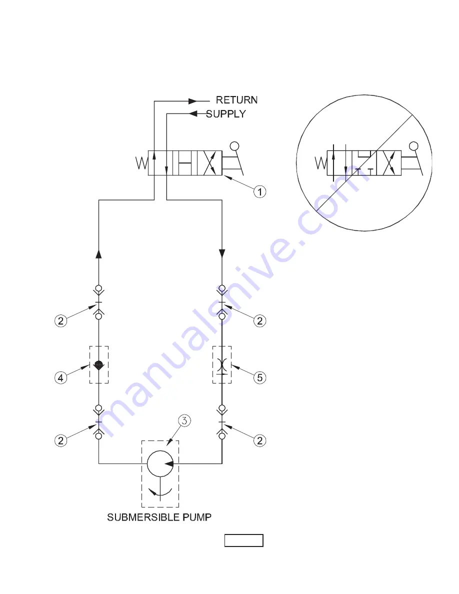
FIGURE 1
TYPICAL HYDRAULIC SCHEMATIC
FOR CUSTOMER SUPPLIED HYDRAULIC POWER SOURCE
DO NOT USE CLOSED CENTER
VALVES!
Return fl ow from the hydraulic motor must be
allowed to return to the oil reservoir to enable the
pump impeller to gradually slow to a stop. Blocking
this fl ow will cause damage to the hydraulic motor
and pump seal!
1. 4 way open center directional valve (must be
operated in forward direction only or use check
valve (4) to prevent reversing).
2. Valve quick disconnect coupling
3. Hydraulic motor driving submersible pump
4. Check valve (Recommended)
5. Flow control (Recommended if hydraulic fl ow is
greater
than
fl ow required by submersible pump
Summary of Contents for PHD13G
Page 10: ...10 FIGURE 2 Model PHD13G...
Page 11: ...11 FIGURE 3 Model PHD13G FIGURE 4...
Page 14: ...14 FIGURE 5 Model PHD20G FIGURE 6...
Page 15: ...15 FIGURE 7 Model PHD20G...


