background image

5

5

4

4

3

3

2

2

1

1

D

D

C

C

B

B

A

A

RB

RA

J_FAN1

1

3

CPU_FAN

6-20-23120-003

KBC_LED

For common design

O P T I O N   (

㗗 ⏎

)

J_KB1

1

24

N850

6-03-08587-FX

6-20-94AF0-124

6-20-94K40-106

KBC LED CONTROL 

Used for 15"

3/10

VGA FAN  CONTROL 

J_FAN2

1

VGA_FAN

3

6-20-23120-003

CPU FAN  CONTROL 

Debug Port

䘥 ⃱

J_KB2

1

24

N870

6-20-94K40-106

KBC_LED

 N870 White LED Keyboard

u s b  c har ge r 

≇傥

,

Pull low 

,

,   pul l   hi g h 

㗪㰺 㚱

N850HC

N870HN

EC MODEL_ID LIST

RA

RB

10K

X

15.4K

10K

10K

4.42K

10K

X

N870HC

N850HN

VOLTAGE

3.3V

2V

1V

0V

Gary_D02 for ALC269-VB7 co-lay

For common design change net name

change TI charger net N.C/ Common design 

change TI charger net N.C/ASM1543 PD

change TI charger net N.C/ASM1543 PD

N870HL

N850HL

10K

10K

1.78K

8.25K

0.5V

1.5V

For common design change net name

For common design 

For common design 

BAV99: 6-06-00099-011

For common design 

For common design 

For N850HL

For common design change name

EC_PECI

KB-SI3

KB-SI2

KB-SO5

KB-SI1

KB-SO3
KB-SO4

KB-SO11

KB-SI6

KB-SI4

KB-SO8

KB-SO7

KB-SO6

KB-SO14

KB-SO2

KB-SO15

KB-SI0

KB-SI5

KB-SO12

KB-SO1

KB-SO10

KB-SO0

KB-SI7

KB-SO9

KB-SO13

BAT_DET

SMC_BAT
SMD_BAT

GPIO9_THERM_ALERT_EC

BAT_VOLT
CPU_FAN

AC_IN#

MODEL_ID

CPU_FAN

CPU_FANSEN

KB-SI3

KB-SI2

KB-SO5

KB-SI1

KB-SO3
KB-SO4

KB-SO11

KB-SI6

KB-SI4

KB-SO8

KB-SO7

KB-SO6

KB-SO14

KB-SO2

KB-SO15

KB-SI0

KB-SI5

KB-SO12

KB-SO1

KB-SO10

KB-SO0

KB-SI7

KB-SO9

KB-SO13

HSPI_SCLK

AUTO_LOAD_PWR

HSPI_MSO

HSPI_MSI

HSPI_CE#

CPU_FANSEN

KBC_WRESET#

KBC_WRESET#

CPU_FAN

BAT_DET
BAT_VOLT

MODEL_ID

3IN1

80PORT_DET#

VBATT_BOOST#

KBCLED

KBC_LED

KBC_LED

VBATT_BOOST#

EC_PECI

VGA_FAN

VGA_FANSEN

VGA_FAN

VGA_FANSEN

GA20

SMD_VGA_THERM

SMC_VGA_THERM

KBC_MUTE#

GC6_FB_EN

3IN1

80PORT_DET#

ALL_SYS_PWRGD_R

VDD3

VDD3

FAN_CPU_5VS

3.3VS

5VS

FAN_CPU_5VS

5VS_KBC

VDD3

VDD3

KBC_AGND

KBC_AGND

KBC_AVDD

VDD3

3.3VS

VDD3

VDD3

KBC_AGND

5VS

5VS_KBC

3.3VS

FAN_VGA_5VS

FAN_VGA_5VS

5VS

5VS_KBC

3.3VS

VDD3

VDD3

H_PECI

4

AIRPLAN_LED#

36

CCD_EN

36

BKL_EN

17

HSPI_CE#

20

HSPI_MSI

20

HSPI_MSO

20

NB_ENAVDD

17,22

LAN_WAKEUP#

20,30,34

SWI#

22

EC_RSMRST#

23

SB_KBCRST#

24

BUF_PLT_RST#

24,30,31,34,36

LPC_FRAME#

24,36

AC_PRESENT

23

LED_ACIN

36

SMI#

24

SERIRQ

24,36

PCLK_KBC

24

LPC_AD3

24,36

LPC_AD2

24,36

LPC_AD1

24,36

LPC_AD0

24,36

KBC_MUTE#

37

AC_IN#

47

SCI#

22

SMC_VGA_THERM

14

SMD_VGA_THERM

14

THERM_VOLT

2

TOTAL_CUR

47

SMC_BAT

38,47

SMD_BAT

38,47

BAT_VOLT

47

BAT_DET

38,47

LED_BAT_FULL

36

LED_BAT_CHG

36

LED_PWR

36

KBC_BEEP

37

EC_SSD_LED#

36

TP_CLK

35

TP_DATA

35

PWR_SW#

39

LID_SW#

17,35

PWR_BTN#

23

H_PROCHOT_EC

4

HSPI_SCLK

20

SUS_PWR_ACK#

23

VBATT_BOOST#

14

dGPU_OVERT_EC

14

GPIO9_THERM_ALERT_EC

14

USB_CHARGE_EN

39,41

3G_EN

29

BT_EN

30

DD_ON

32,33,39,41,50

SUSB#_PCH

23,39

SUSC#_PCH

23,39

WLAN_PWR_EN

30

WLAN_EN

30

3G_PWR_EN

29

SUS_WARN#

23

PM_PWROK

21

ALL_SYS_PWRGD

4,17,21,44

SLP_SUS#

23,40,45

SLP_SUS#_EC

23

ME_W E

23

ASM1142_PORST#_R

31

PCH_SLP_WLAN#

23

GC6_FB_EN

14,24,49

dGPU_PWR_EN

14,24,50

EAPD

35,37

80PORT_DET#

30

3IN1

30

EC_EN

39

SMC_BAT

38,47

SMD_BAT

38,47

BAT_DET

38,47

ASM1543_I_SEL1

23,33

ASM1543_I_SEL0

23,33

ALL_SYS_PWRGD_R

21

Title

Size

Document Number

R e v

Date:

Sheet

o f

6-71-N85L0-D01

D01

[38]KBC-ITE IT8587

Custom

38

56

Tuesday, March 21, 2017

ᙔ!Ϻ!ႝ!တ!!DMFWP!DP/

D01

Title

Size

Document Number

R e v

Date:

Sheet

o f

6-71-N85L0-D01

D01

[38]KBC-ITE IT8587

Custom

38

56

Tuesday, March 21, 2017

ᙔ!Ϻ!ႝ!တ!!DMFWP!DP/

D01

Title

Size

Document Number

R e v

Date:

Sheet

o f

6-71-N85L0-D01

D01

[38]KBC-ITE IT8587

Custom

38

56

Tuesday, March 21, 2017

ᙔ!Ϻ!ႝ!တ!!DMFWP!DP/

D01

C502

10u_6.3V_X5R_06

_

R452

4.7K_04

R633

*0_04

R269

*10mil_short

R312

*10mil_short

J_FAN2

1251-3AW-S-02(N)

1
2
3

R366

4.7K_04

U4

NCT3940S-A

VOUT

3

GND

5

VIN

2

FON

1

VSET

4

GND

6

GND

8

GND

7

R311

33_04

R337

100K_04

.

L21

HCB1005KF-121T20

C459

10u_6.3V_X5R_06

C452

10p_50V_NPO_04

R267

*10K_04

C481

0.1u_16V_Y5V_04

D18

BAV99 RECTIFIER

A

C

AC

R268

*10mil_short

R310

*10mil_short

R308

1.5K_04

C20

0.1u_10V_X5R_04

J_KB1

85208-24051

N85HL

24

23

22

14

12

11

21

8

20

19

6

5

18

4

17

10

9

7

3

2

1

16

15

13

25

26

C317

0.1u_10V_X7R_04

WHITE_KB

U15

NCT3940S-A

WHITE_KB

VOUT

3

GND

5

VIN

2

FON

1

VSET

4

GND

6

GND

8

GND

7

C482

0.1u_16V_Y5V_04

K/B MATRIX

FLASH

LPC

SMBUS

PS/2

PWM

UART

DAC

CLOCK

IT8587

CIR

ADC

WAKE UP

PWM/COUNTER

LPC/WAKE UP

EXT GPIO

GP INTERRUPT

WAKE UP

GPIO

U32

IT8587E/FX

WRST#

14

LPCCLK

13

LAD0

10

LAD1

9

LAD2

8

LAD3

7

LFRAME#

6

( PD )LPCPD#/WUI6/GPE6

17

SERIRQ

5

ECSMI#/GPD4( PU )

15

ECSCI#/GPD3( PU )

23

GA20/GPB5

126

KBRST#/GPB6( PU )

4

KSI0/STB#

58

KSI1/AFD#

59

KSI2/INIT#

60

KSI3/SLIN#

61

KSI4

62

KSI5

63

KSI6

64

KSI7

65

KSO0/PD0

36

KSO1/PD1

37

KSO2/PD2

38

KSO3/PD3

39

KSO4/PD4

40

KSO5/PD5

41

KSO6/PD6

42

KSO7/PD7

43

KSO8/ACK#

44

KSO9/BUSY

45

KSO10/PE

46

KSO11/ERR#

51

KSO12/SLCT

52

KSO13

53

KSO14

54

KSO15

55

VC

C

11

VST

BY

26

VST

BY

50

VST

BY

92

VST

BY

114

VST

BY

127

VST

BY

121

VBA

T

3

AVC

C

74

PS2CLK0/GPF0( PU )

85

PS2DAT0/GPF1( PU )

86

PS2CLK1/GPF2( PU )

87

( PD )TMRI0/WUI2/GPC4

120

( PD )TMRI1/WUI3/GPC6

124

LPCRST#/WUI4/GPD2( PU )

22

( PD )WUI5/GPE5

35

PWRSW/GPE4( PU )

125

RI1#/WUI0/GPD0( PU )

18

RI2#/WUI1/GPD1( PU )

21

( PD )RING#/PWRFAIL#/LPCRST#/GPB7

112

TXD/GPB1( PU )

109

RXD/GPB0( PU )

108

( PD )CTX/GPB2

123

PS2DAT1/GPF3( PU )

88

PS2CLK2/GPF4( PU )

89

PS2DAT2/GPF5( PU )

90

( PD )TACH0/GPD6

47

( PD )TACH1/GPD7

48

PWM0/GPA0( PU )

24

PWM1/GPA1( PU )

25

PWM2/GPA2( PU )

28

PWM3/GPA3( PU )

29

PWM4/GPA4( PU )

30

PWM5/GPA5( PU )

31

PWM6/GPA6( PU )

32

PWM7/GPA7( PU )

34

ADC0/GPI0

66

ADC1/GPI1

67

ADC2/GPI2

68

ADC3/GPI3

69

ADC4/GPI4

70

ADC5/GPI5

71

ADC6/GPI6

72

ADC7/GPI7

73

VSS

1

VSS

12

VSS

27

VSS

49

VSS

122

VSS

113

AVS

S

75

CK32KE

2

CK32K

128

DAC3/GPJ3

79

DAC2/GPJ2

78

GPJ1

77

GPJ0

76

( PD )EGCS#/GPE2

83

( PD )EGCLK/GPE3

84

( PD )EGAD/GPE1

82

GINT/GPD5( PU )

33

L80LLAT/GPE7( PU )

20

VSS

91

DAC5/GPJ5

81

DAC4/GPJ4

80

PWUREQ#/GPC7( PU )

16

( PD )CRX/GPC0

119

( PD )KSO16/GPC3

56

( PD )KSO17/GPC5

57

( PD )GPH0/ID0

93

( PD )GPH1/ID1

94

( PD )GPH2/ID2

95

( PD )GPH3/ID3

96

( PD )GPH4/ID4

97

( PD )GPH5/ID5

98

( PD )GPH6/ID6

99

( PD )GPG1/ID7

107

SMCLK0/GPB3

110

SMDAT0/GPB4

111

SMCLK1/GPC1

115

SMDAT1/GPC2

116

SMCLK2/GPF6( PU )

117

SMDAT2/GPF7( PU )

118

FLFRAME#/GPG2

100

FLAD0/SCE#

101

FLAD1/SI

102

FLAD2/SO

103

FLAD3/GPG6

104

FLCLK/SCK

105

( PD )FLRST#/WUI7/GPG0/TM

106

( PD )L80HLAT/GPE0

19

R274

10K_04

R289

10K_04

R326

10K_04

R272

*10mil_short

C479

0.1u_10V_X7R_04

R288

1.5K_04

R276

10K_1%_04

J_80DEBUG1

85204-04001

DEBUG PORT

1
2
3
4

J_KB2

85208-24051

N87HL

24

23

22

14

12

11

21

8

20

19

6

5

18

4

17

10

9

7

3

2

1

16

15

13

25

26

C429

0.1u_16V_Y5V_04

C477

0.1u_10V_X7R_04

R309

43_1%_04

J_FAN1

1251-3AW-S-02(N)

1
2
3

R327

10K_04

R617

*10K_04

R290

33_04

J_KBC_LED2

50541-00601-002

N87_WHITE

1

2

3

4

5

6

R255

*10mil_short

C672

0.1u_16V_Y5V_04

R275

*0_04

R273

10K_04

CHANGE

R635

*0_04

R5

6

4.

7K_04

D16

BAV99 RECTIFIER

A

C

AC

R632

*0_04

C318

10u_6.3V_X5R_06

N87_WHITE

R324 *0_04

C234

10u_6.3V_X5R_06

D17

BAV99 RECTIFIER

A

C

AC

U1

NCT3940S-A

VOUT

3

GND

5

VIN

2

FON

1

VSET

4

GND

6

GND

8

GND

7

C478

0.1u_16V_Y5V_04

C480
0.1u_16V_Y5V_04

J_KBC_LED1

50541-00601-002

N85_WHITE

1

2

3

4

5

6

R325 0_04

R270

10K_04

W/O CHARGER

R4

5

4.

7K_04

C430

0.1u_16V_Y5V_04

C411

1u_6.3V_X5R_04

R271

10K_04

CHARGER

R256

8.25K_04

N870HL

ᶲẞ

1.78K

C198

1u_6.3V_X5R_04

C319

10u_6.3V_X5R_06

N85_WHITE

Sheet 37 of 55

KBC-ITE IT8587

Schematic  Diagrams

B - 38   KBC-ITE IT8587 

B.Schematic Diagrams

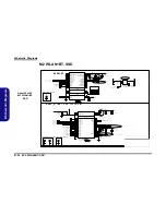
KBC-ITE IT8587

Summary of Contents for N850HL

Page 1: ...N850HL...

Page 2: ......

Page 3: ...Preface I Preface Notebook Computer N850HL Service Manual...

Page 4: ...ole or in part be reproduced translated transmitted or reduced to any machine readable form without prior consent from the vendor manufacturer or creators of this publica tion except for copies kept b...

Page 5: ...ervicing and or upgrading components of the N850HL se ries notebook PC The following information is included Chapter 1 Introduction provides general information about the location of system elements a...

Page 6: ...ng 3 Do not use the telephone to report a gas leak in the vicinity of the leak 4 Use only the power cord and batteries indicated in this manual Do not dispose of batteries in a fire They may explode C...

Page 7: ...down properly and don t forget to save your work Remember to periodically save your data as data may be lost if the battery is depleted Do not expose the computer to any shock or vibration Do not plac...

Page 8: ...pose If you do not have access to a compatible outlet have a qualified electrician install one When you want to unplug the power cord be sure to disconnect it by the plug head not by its wire Make sur...

Page 9: ...r hands or metal objects Battery Guidelines The following can also apply to any backup batteries you may have If you do not use the battery for an extended period then remove the battery from the comp...

Page 10: ...n plug the AC power cord into an outlet and connect the AC power cord to the AC DC adapter and leave it there for 6 seconds or longer Remove the adapter cord from the computer s DC In jack and then pl...

Page 11: ...Preface IX Preface...

Page 12: ...Preface X Preface...

Page 13: ...he System Memory RAM 2 10 Removing and Installing the M 2 SSD Module 2 11 Removing the Wireless LAN Module 2 13 Wireless LAN Combo 3G LTE Module Cables 2 14 Removing the 3G Module 2 15 Part Lists A 1...

Page 14: ...3 GPU Power 1 2 B 44 GPU Power 2 2 B 45 AC_In Charger B 46 VCore VCCSA B 47 VCore Output Stage B 48 VCCGT B 49 VCCGT Output Stage B 50 Click Board B 51 LED Board B 52 Power Board B 53 Audio Board 1 2...

Page 15: ...is shipped with the computer Operating systems e g Windows 10 etc have their own manuals as do application softwares e g word processing and database programs If you have questions about those program...

Page 16: ...PI Flash ROM AMI BIOS Memory Two 260 Pin SO DIMM Sockets Supporting DDR4 2400MHz Memory Memory Expandable up to 32GB The real memory operating frequency depends on the FSB of the processor LCD Options...

Page 17: ...the ports Card Reader Embedded Multi In 1 Card Reader MMC MultiMedia Card RS MMC SD Secure Digital Mini SD SDHC SDXC M 2 Slots Slot 1 for WLAN and Bluetooth Combo Module Slot 2 for SATA PCIe Gen3 x4 S...

Page 18: ...n 1 Introduction External Locator Top View with LCD Panel Open Figure 1 Top View 1 PC Camera 2 PC Camera LED When the PC camera is in use the LED will be illuminated 3 Built In Array Microphone 4 LCD...

Page 19: ...tion External Locator Front Right Side Views Figure 2 Front View 1 LED Indicator Figure 3 Right Side View 1 Headphone Out Jack 2 Microphone In Jack 3 USB 2 0 Port 4 USB 3 0 USB 3 1 Gen 1 Type A Port 5...

Page 20: ...iew 1 DC In Jack 2 RJ 45 LAN Jack 3 External Monitor Port 4 HDMI Out Port 5 USB 3 0 USB 3 1 Gen 1 Type C Port Or Factory Option USB 3 1 Gen 2 Type C Port 6 USB 3 0 USB 3 1 Gen 1 Type A Port Or Factory...

Page 21: ...om View 1 7 1 Introduction External Locator Bottom View Figure 6 Bottom View 1 Battery 2 Vent 3 Speakers Overheating To prevent your com puter from overhea ting make sure no thing blocks any vent whil...

Page 22: ...Introduction 1 8 Mainboard Overview Top Key Parts 1 Introduction Mainboard Overview Top Key Parts Figure 7 Mainboard Top Key Parts 1 KBC ITE IT8587 1...

Page 23: ...Key Parts 1 GPU 2 CPU 3 Memory Slots DDR4 SO DIMM 4 Mini Card Connector WLAN Module 5 PCH 6 CMOS Battery 7 M 2 Card Connector SSD Module Introduction Mainboard Overview Bottom Key Parts 1 9 1 Introduc...

Page 24: ...w Top Connectors Figure 9 Mainboard Top Connectors 1 DC In Jack 2 RJ 45 LAN Jack 3 External Display Port 4 HDMI Out Port 5 USB Port 3 0 3 1 Type C Connector 6 USB Port 3 0 3 1 Type A Connector 7 Multi...

Page 25: ...d Overview Bottom Connectors 1 11 1 Introduction Mainboard Overview Bottom Connectors Figure 10 Mainboard Bottom Connectors 1 CCD Connector 2 Fan Connector 3 HDD Connector 4 Speaker Connector 5 LCD Co...

Page 26: ...Introduction 1 12 1 Introduction...

Page 27: ...mbly process easier each section may have a box in the page margin Information contained under the figure will give a synopsis of the sequence of procedures involved in the disassembly procedure A box...

Page 28: ...ing the connection make sure the connector is oriented in the same way The pin1 side is usually not indicated Pressure sockets for multi wire connectors To release this connector type grasp it at its...

Page 29: ...he computer When handling a printed circuit board do not use gloves or other materials which allow static electricity buildup We suggest that you use an anti static wrist strap instead 8 Beware of cor...

Page 30: ...ve the HDD page 2 7 To remove the System Memory 1 Remove the battery page 2 5 2 Remove the HDD page 2 7 3 Remove the system memory page 2 9 To remove the M 2 SSD 1 Remove the battery page 2 5 2 Remove...

Page 31: ...he arrow Figure 1a 3 Slide the latch in the direction of the arrow 4 While holding the latch lift the battery Figure 1b out of the compartment Figure 1c 1 2 2 3 Figure 1 Battery Removal a Slide the la...

Page 32: ...g collar socket by using a flat head screwdriver to pry the locking collar pins away from the base Figure 2b 5 Carefully lift the keyboard off the computer Figure 2c 1 2 3 4 5 6 7 7 8 6 6 7 8 8 7 8 8...

Page 33: ...tery page 2 5 2 Remove the SD card cover and screws Figure 3a 3 Carefully push to release the bottom case from point and then lift it up from point to release the bottom case and ports as indicated by...

Page 34: ...ning New HDD s are blank Before you begin make sure You have backed up any data you want to keep from your old HDD You have all the CD ROMs and FDDs required to install your operating system and progr...

Page 35: ...d module if necessary 5 Insert a new module holding it at about a 30 angle and fit the connectors firmly into the memory slot 6 The module will only fit one way as defined by its pin alignment Make su...

Page 36: ...turn it over remove the battery page 2 5 2 The M 2 SSD module will be visible at point on the mainboard Figure 6a 3 Remove the screw Figure 6b 4 The M 2 SSD module Figure 6c will pop up and you can re...

Page 37: ...Figure 7a 3 Carefully disconnect the cables and then remove the screw Figure 7b 4 The Wireless LAN module Figure 7c will pop up and you can remove it from the computer 1 2 3 4 5 b c a 2 3 5 1 5 4 5 Wi...

Page 38: ...t labelled The cables covers each cable will have either a black or transparent cable cover are color coded for iden tification as outlined in the table below Cable 1 is usually connected to antenna 1...

Page 39: ...point Figure 8a 3 Carefully disconnect the cables and then remove the screw from the module Figure 8b 4 The module will pop up Figure 8c 5 Lift the module up and off the computer Figure 8d Figure 8 3G...

Page 40: ...ift at the upper point as indicated by the arrows and slightly push and lift up the inner frame at the middle points as indicated by the arrows and then run your fingers around the inner frame at the...

Page 41: ...isassembly 5 Disconnect the cable Figure 10c 6 Remove the CCD module Figure 10d 7 Reverse the process to install a new CCD module 10 11 d c 11 10 11 CCD Module Figure 10 CCD Removal cont d c Disconnec...

Page 42: ...Disassembly 2 16 2 Disassembly...

Page 43: ...our organization may use a different system so be sure to cross check any relevant documentation Note Some assemblies may have parts in common especially screws However the part lists DO NOT indicate...

Page 44: ...Illustration Location The following table indicates where to find the appropriate part list illustration Table A 1 Part List Illustration Location Part Top page A 3 Bottom page A 4 Main Board page A 5...

Page 45: ...Top A 3 A Part Lists Top Figure A 1 Top...

Page 46: ...A 4 Bottom A Part Lists Bottom Figure A 2 Bottom...

Page 47: ...Main Board A 5 A Part Lists Main Board Figure A 3 Main Board...

Page 48: ...A 6 HDD A Part Lists HDD Figure A 4 HDD...

Page 49: ...LCD A 7 A Part Lists LCD Figure A 5 LCD...

Page 50: ...A 8 A Part Lists...

Page 51: ...4 CHB SO DIMM Page B 10 ASM 1142 2142 Page B 31 Power Switch Board Page B 52 VGA PCI E Interface Page B 11 ASM Power Page B 32 Hall Sensor Board Page B 53 VGA Frame Buffer Interface Page B 12 USB Char...

Page 52: ...8 port SHEET 35 USB3 0 USB3 1 USB2 0 PORT2 USB2 0 PORT6 USB2 0 PORT1 SATA III PORT2 Power 1 05V 1 5V 3 3V VCORE VR12 5 1866 2133 MHz DDR4 1 2V Optional SHEET 38 TPM 2 0 AC IN SHEET 46 VCCSA SHEET 45...

Page 53: ...7 EDP_TXP 0 D29 EDP_TXN 0 E29 EDP_TXP 1 F28 EDP_TXN 3 B28 EDP_TXP 3 C28 EDP_AUXP C26 EDP_AUXN B26 EDP_DISP_UTIL A33 EDP_RCOMP D37 PROC_AUDIO_CLK G27 PROC_AUDIO_SDI G25 PROC_AUDIO_SDO G29 DDI1_AUXP D27...

Page 54: ...N 0 BR5 DDR0_PAR AG3 DDR0_MA 14 DDR0_CAA 9 DDR0_BG 1 AU2 DDR0_MA 15 DDR0_CAA 8 DDR0_ACT AU3 DDR0_MA 13 DDR0_CAB 0 DDR0_MA 13 AE3 DDR0_MA 12 DDR0_CAA 6 DDR0_MA 12 AU4 DDR0_MA 11 DDR0_CAA 7 DDR0_MA 11 A...

Page 55: ...CLK_R_DP 25 PCH_CPU_PCIBCLK_R_DN 25 PCH_CPU_PCIBCLK_R_DP 25 CPU_24MHZ_R_DN 25 CPU_24MHZ_R_DP 25 H_PWRGD 23 PLTRST_CPU_N 22 H_PM_SYNC 22 H_SKTOCC_N 24 DDR_VTT_PG_CTRL 42 H_CPU_SVIDCLK 44 H_CPU_SVIDDAT...

Page 56: ...EOPIO BR15 R400 49 9_1 _04 C505 390uF_2 5V_10m_6 3 6 C180 1u_6 3V_X6S_04 C552 22u_6 3V_X5R_06 R419 49 9_1 _04 C179 1u_6 3V_X6S_04 C38 10u_4V_X6S_06 C248 1u_6 3V_X6S_04 C246 1u_6 3V_X6S_04 C217 22u_6 3...

Page 57: ...VCCIO AG12 VCCSA M34 VCCSA M33 VCCSA M32 VCCSA M31 VCCSA M30 VCCSA L38 VCCSA M29 VCCSA L37 VCCSA L36 VCCSA L32 VCCSA L35 VCCSA L31 VCCSA K35 VCCSA K34 VCCSA K29 VCCSA J30 VCCIO_SENSE H14 VSSIO_SENSE...

Page 58: ...CGT BB32 VCCGT BA31 VCCGT BA30 VCCGT BA29 VCCGT BA14 VCCGT AV30 VCCGT AV29 VCCGT AV31 VCCGT AV32 VCCGT AV33 VCCGT AV35 VCCGT AV34 VCCGT AV36 VCCGT AW14 VCCGT AW31 VCCGT AW33 VCCGT AW32 VCCGT AW34 VCCG...

Page 59: ...03 10u_6 3V_X5R_06 C376 10u_6 3V_X5R_06 C353 1u_6 3V_X5R_04 C612 1u_6 3V_X5R_04 C648 330uF_2 5V_12m_6 6 6 6 4 2 C362 2 2u_6 3V_X5R_04 J_DIMMA_2B D4AR0 26001 1P52 VDD19 163 VDD18 160 VDD17 159 VDD16 15...

Page 60: ...11 141 VDD10 136 VDD9 135 VDD8 130 VDD7 129 VDD6 124 VDD5 123 VDD4 118 VDD3 117 VDD2 112 VDD1 111 VSS 251 VSS 247 VSS 243 VSS 239 VSS 235 VSS 231 VSS 227 VSS 223 VSS 217 VSS 213 VSS 209 VSS 205 VSS 20...

Page 61: ...X7 AG13 PEX_RX6 AG12 PEX_RX6 AB15 PEX_TX6 AC15 PEX_TX6 AF12 PEX_RX5 AE12 PEX_RX5 AC14 PEX_TX5 AD14 PEX_TX5 AE10 PEX_RX4 AF10 PEX_RX4 AC13 PEX_TX4 AB13 PEX_TX4 AG10 PEX_RX3 AG9 PEX_RX3 AB12 PEX_TX3 AC1...

Page 62: ...QS_WP0 U25 FBA_DQM7 AA25 FBA_DQM6 W24 FBA_DQM5 P24 FBA_DQM4 C22 FBA_DQM3 C17 FBA_DQM2 D14 FBA_DQM1 D19 FBA_DQM0 W25 FBA_D63 W27 FBA_D62 V27 FBA_D61 V26 FBA_D60 R27 FBA_D59 N27 FBA_D58 T25 FBA_D57 R26...

Page 63: ..._1 _04 COMMON BGA170 INS1220714 U151B K4G80325FB HC03 CHANGE J10 SEN J13 ZQ J14 VREFC V5 NC_RFU_V5 A5 NC_RFU_A5 J11 CLK J12 CLK J3 CKE J2 RESET J5 RFU_A12 K4 A7_A8 K5 A6_A11 K10 A5_BA1 K11 A4_BA2 H10...

Page 64: ...RAS C28 0 1u_10V_X7R_04 R98 931_1 _04 R99 931_1 _04 C30 1u_6 3V_X5R_04 C32 1u_6 3V_X5R_04 R16 0_04 NC NC NC NC NC NC NC NC GND x32 x16 MIRRORED NC COMMON BGA170_MIRR INS1226066 U152A K4G80325FB HC03 C...

Page 65: ..._PWRGD 5 GC6_FB_EN 6 GC6_FB_EN_PCH 7 PLT_RST 8 dGPU_RST _PCH 9 GPU_PEX_RST 10 FBVDDQ_EN 20 PEX_VDD_EN 19 NVVDDS_EN 18 NVVDD_EN 17 3V3_SYS_EN 16 1V8_MAIN_EN 15 1V8_AON_EN 14 GPIO4_1V8_MAIN_EN 13 dGPU_P...

Page 66: ...GND E25 GND E22 GND E20 GND E2 GND E17 GND E14 GND E11 GND B8 GND B5 GND B27 GND B23 GND B20 GND B17 GND B14 GND B11 GND B1 GND AB14 GND AG26 GND AG2 GND AF8 GND AF5 GND AF23 GND AF20 GND AF17 GND AF1...

Page 67: ...2017 DMFWP DP D01 Title Size Document Number Re v Date Sheet o f 6 71 N85L0 D01 D01 17 PANEL INVERTER A3 17 56 Tuesday March 21 2017 DMFWP DP D01 C539 0 1u_10V_X7R_04 R486 0_04 D30 BAV99N3 A C AC J_LC...

Page 68: ...t Number Re v Date Sheet o f 6 71 N85L0 D01 D01 18 CRT A3 18 56 Tuesday March 21 2017 DMFWP DP D01 Title Size Document Number Re v Date Sheet o f 6 71 N85L0 D01 D01 18 CRT A3 18 56 Tuesday March 21 20...

Page 69: ...S_DATA2 RR TMDS_DATA0J TMDS_DATA0 J TMDS_CLOCK J TMDS_CLOCKJ TMDS_CLOCK TMDS_CLOCK TMDS_DATA0 TMDS_DATA0 TMDS_DATA1 J TMDS_DATA1J TMDS_DATA1 TMDS_DATA1 TMDS_DATA2 J TMDS_DATA2J TMDS_DATA2 TMDS_DATA2 H...

Page 70: ...ent Number Re v Date Sheet o f 6 71 N85L0 D01 D01 20 PCH 1 12 SPI SMBUS A3 20 56 Tuesday March 21 2017 DMFWP DP D01 Title Size Document Number Re v Date Sheet o f 6 71 N85L0 D01 D01 20 PCH 1 12 SPI SM...

Page 71: ...ocument Number Re v Date Sheet o f 6 71 N85L0 D01 D01 21 PCH 2 12 DMI PCIE USB2 0 A3 21 56 Tuesday March 21 2017 DMFWP DP D01 C336 0 1u_10V_X7R_04 RN8 10K_8P4R_04 1 2 3 4 5 6 7 8 C620 0 1u_10V_X7R_04...

Page 72: ...FAN_TACH_6 T45 GPP_G7 FAN_TACH_7 T44 PCIE11_TXP B33 PCIE11_TXN C33 PCIE11_RXP K31 PCIE11_RXN L31 GPP_F10 SCLOCK AB33 GPP_F11 SLOAD AB35 GPP_F13 SDATAOUT0 AA44 GPP_F12 SDATAOUT1 AA45 PCIE14_TXN SATA1B...

Page 73: ...PCH 4 12 HDA SMBUS RTC A3 23 56 Tuesday March 21 2017 DMFWP DP D01 Title Size Document Number Re v Date Sheet o f 6 71 N85L0 D01 D01 23 PCH 4 12 HDA SMBUS RTC A3 23 56 Tuesday March 21 2017 DMFWP DP D...

Page 74: ...N85L0 D01 D01 24 PCH 5_6 12 DPP ESPI USB3 0 A3 24 56 Tuesday March 21 2017 DMFWP DP D01 Title Size Document Number Re v Date Sheet o f 6 71 N85L0 D01 D01 24 PCH 5_6 12 DPP ESPI USB3 0 A3 24 56 Tuesda...

Page 75: ...17 DMFWP DP D01 R482 10mil_short C577 10p_50V_NPO_04 C578 10p_50V_NPO_04 R556 1M_1 _04 R2 10K_04 X4 CM200C_32 768KHZ CM200S 1 4 3 2 C625 15p_50V_NPO_04 SPT H_PCH 7 OF 12 REV 1 3 U45G HM175 GPP_A16 CLK...

Page 76: ...20mil_04 R158 20mil_04 C298 1u_6 3V_X5R_04 C271 0 1u_10V_X7R_04 R159 20mil_04 R126 20mil_04 C269 1u_6 3V_X5R_04 C273 0 1u_10V_X7R_04 R127 20mil_04 C268 1u_6 3V_X5R_04 C270 1u_6 3V_X5R_04 C299 0 1u_10V...

Page 77: ...S M35 VSS M42 VSS N10 VSS N15 VSS N19 VSS N22 VSS N24 VSS N35 VSS N36 VSS N4 VSS N41 VSS N5 VSS P17 VSS P19 VSS P22 VSS P45 VSS R10 VSS R14 VSS R22 VSS R29 VSS R33 VSS R38 VSS R5 VSS T1 VSS T2 VSS T4...

Page 78: ...SS A4 VSS B44 VSS B45 VSS A42 VSS D45 VSS BE44 VSS BD44 VSS BD45 VSS BD2 PCH_TRIGIN AK1 PCH_TRIGOUT AL2 CPU_TRST AY5 PRDY AT4 PREQ AT3 RSVD P24 RSVD R24 RSVD AN29 RSVD P29 RSVD N29 RSVD R27 RSVD P31 R...

Page 79: ..._Y5V_04 C702 0 1u_16V_Y5V_04 LTE R350 10_06 LTE R613 0_06 LTE C703 470p_50V_X7R_04 LTE T141 Q30A MTS3572G6 LTE S2 4 D2 3 G2 5 Q31 UK3018 LTE G D S C487 0 1u_16V_Y5V_04 LTE Q30B MTS3572G6 LTE S1 2 D1 6...

Page 80: ...6V_Y5V_04 R629 0_04 C391 22u_6 3V_X5R_08 C352 22u_6 3V_X5R_08 U23 uP7553 EN 3 VIN 5 VIN SS 4 VOUT 1 GND 2 R620 0_04 R621 10K_04 C710 0 1u_10V_X7R_04 C656 0 1u_10V_X7R_04 R619 0_04 R228 10K_04 C657 0 1...

Page 81: ...2017 DMFWP DP D01 R215 100K_04 C634 0 1u_16V_Y5V_04USB3 1 R178 0_04USB3 1_1142 C314 0 1u_16V_Y5V_04USB3 1 C642 0 1u_16V_Y5V_04 USB3 1 R194 0_04 USB3 1 R220 0_04 USB3 1 C324 0 22u_10V_X5R_04 USB3 1 C3...

Page 82: ...1mm 1 2 C386 0 1u_10V_X7R_04 USB3 1_2142 G5016 U22 USB3 1 CT2 10 OUT2 8 EN2 5 VBIAS 4 IN2 6 GND 11 EN1 3 CT1 12 OUT1 13 IN1 1 IN1 2 OUT1 14 IN2 7 OUT2 9 GND 15 PC55 0 1u_10V_X5R_04 USB3 1_2142 PJ26 1m...

Page 83: ...Date Sheet o f 6 71 N85L0 D01 D01 33 USB3 0 CON USB CHARGER Custom 33 56 Tuesday March 21 2017 DMFWP DP D01 Title Size Document Number Rev Date Sheet o f 6 71 N85L0 D01 D01 33 USB3 0 CON USB CHARGER C...

Page 84: ...31 36 38 LAN_WAKEUP 20 30 38 Title Size Document Number Re v Date Sheet o f 6 71 N85L0 D01 D01 34 CARD READER LAN RTL8411B A3 34 56 Tuesday March 21 2017 DMFWP DP Title Size Document Number Re v Date...

Page 85: ...FWP DP Title Size Document Number Re v Date Sheet o f 6 71 N85L0 D01 D01 35 HDD CLICK TP AUDIO HALL CON A3 35 56 Tuesday March 21 2017 DMFWP DP Title Size Document Number Re v Date Sheet o f 6 71 N85L...

Page 86: ...C_SSD_LED 38 AIRPLAN_LED 38 LED_BAT_FULL 38 LED_BAT_CHG 38 LED_PWR 38 LED_ACIN 38 M2M_SSD1_LED 30 Title Size Document Number Re v Date Sheet o f 6 71 N85L0 D01 D01 36 LED CCD TPM POWER SW CON A3 36 56...

Page 87: ...ate Sheet o f 6 71 N85L0 D01 D01 37 AUDIO CODEC ALC269 VC2 A3 37 56 Tuesday March 21 2017 DMFWP DP D01 Title Size Document Number Re v Date Sheet o f 6 71 N85L0 D01 D01 37 AUDIO CODEC ALC269 VC2 A3 37...

Page 88: ...R452 4 7K_04 R633 0_04 R269 10mil_short R312 10mil_short J_FAN2 1251 3AW S 02 N 1 2 3 R366 4 7K_04 U4 NCT3940S A VOUT 3 GND 5 VIN 2 FON 1 VSET 4 GND 6 GND 8 GND 7 R311 33_04 R337 100K_04 L21 HCB1005KF...

Page 89: ...5 4 3 R342 10K_04 C474 470p_50V_X7R_04 G5016 U34 CT2 10 OUT2 8 EN2 5 VBIAS 4 IN2 6 GND 11 EN1 3 CT1 12 OUT1 13 IN1 1 IN1 2 OUT1 14 IN2 7 OUT2 9 GND 15 R335 100_04 R336 10K_04 S D G Q25A MTDK3S6R 2 6 1...

Page 90: ...R 2 6 1 G5016 U42 CT2 10 OUT2 8 EN2 5 VBIAS 4 IN2 6 GND 11 EN1 3 CT1 12 OUT1 13 IN1 1 IN1 2 OUT1 14 IN2 7 OUT2 9 GND 15 R68 100K_04 R357 10mil_short C557 0 1u_16V_Y5V_04 C559 220p_50V_NPO_04 EMR5 5 1_...

Page 91: ...PR295 0_04 PD8 CSOD140SH A C PC80 4 7u_25V_X5R_08 PR145 30K_1 _06 PQ36 QM3004M3 4 5 2 5 5 3 1 5 PR296 0_04 PC209 0 1u_10V_X7R_04 PR289 10mil_short PU15 TPS51125ARGER VREF 3 EN1 1 VFB1 2 TONSEL 4 LDO5...

Page 92: ...6 PR281 402K_1 _04 EMC2 2200p_50V_X7R_04 PR128 100K_04 C432 0 1u_16V_Y5V_04 Q21 2SK3018S3 G D S PC189 4 7u_25V_X5R_08 R590 10K_04 U24 uP1804A VCC 1 BUS_SEL 2 GND 3 SDA 4 SCL 5 NC 6 NC 7 OUT 8 PJ58 2mm...

Page 93: ...171 1u_16V_X5R_06 PR73 374_1 _04 PC158 47u_2 5V_X6S_08 PC149 1u_16V_X5R_06 PL11 CMME063T R15MS0R907 1 2 PC26 0 47u_16V_X7R_06 PC144 0 1u_25V_X7R_06 RT9610B PU10 BOOT 4 PWM 5 EN 1 VCC 8 UGATE 3 PHASE 2...

Page 94: ...PR213 10K_06 PC20 100p_50V_X7R_04 PR41 100_04 PR10 56K_1 _04 RT2 100k_1 _04_NTC 1 2 PR34 100K_1 _04 PR191 0_04 PR57 680_1 _04 PR16 0_04 RT4 100k_1 _04_NTC 1 2 PR61 499K_1 _06 PR66 1_1 _06 PC17 1000p_...

Page 95: ...itle Size Document Number Re v Date Sheet o f 6 71 N85L0 D01 D01 45 1 0DX_VCCSTG VCCSFR_OC 3 3VA A3 45 56 Tuesday March 21 2017 DMFWP DP D01 Title Size Document Number Re v Date Sheet o f 6 71 N85L0 D...

Page 96: ...h 21 2017 DMFWP DP D01 PC160 390uF_2 5V_10m_6 3 6 PC39 15p_50V_NPO_04 PR81 20mil_04 PC30 0 1u_50V_Y5V_06 PR84 100_04 PR70 0_06 PC37 0 01u_16V_X7R_04 PC36 1u_6 3V_X5R_04 PR69 100K_04 PR72 2 2_04 PJ10 1...

Page 97: ..._08 PR48 10_04 PQ20 QM3006M3 4 5 2 5 5 3 1 5 PR31 20K_04 PR29 10K_04 PR160 10K_1 _04 PC107 4 7u_25V_X7R_08 PC90 10u_25V_X5R_08 PD2 SS1040WG A C JBAT1 C144DF 105A8 L N87RC_RN 1 2 3 4 5 PD11 MDL914S2 A...

Page 98: ...OD 16 UGATE2 17 BOOT2 18 PHASE2 19 ISEN3 13 ISEN2 14 ISEN1 15 PWM3 22 PC94 4700p_50V_X7R_04 PR174 100_04 PR207 0_04 PC163 330uF_2V_5 4 2 PC105 4 7u_25V_X7R_08 PR223 4 7K_1 _04 SLG PC104 4 7u_25V_X7R_0...

Page 99: ...PR264 0_04 SLG C587 1000p_50V_X7R_04 S D G Q35B MTDK3S6R 5 3 4 PR117 10K_04 PC177 4 7u_25V_X5R_08 PR265 2 2_1 _06 U16 74AHC1G32GW SLG GND 3 B 2 A 1 Y 4 Vcc 5 PC172 390uF_2 5V_10m_6 3 6_m PR99 15_06 S...

Page 100: ...71RE1U 6 FB 8 VCC 9 VIN 2 SW 3 SW 10 VIN 4 PGOOD 5 EN 11 THERM 1 NC 7 NC PR262 0_04 SLG PR273 10K_1 _04 PJ46 3mm 1 2 PC184 22u_6 3V_X5R_08 PR274 160K_04 PJ16 OPEN_2A 1 2 R187 100_06 PR225 10K_04 PL13...

Page 101: ...51 AUDIO BOARD A3 51 56 Tuesday March 21 2017 DMFWP DP Title Size Document Number Re v Date Sheet o f 6 71 N8508 D03 D01 51 AUDIO BOARD A3 51 56 Tuesday March 21 2017 DMFWP DP AC26 0 1u_10V_X7R_04 AL6...

Page 102: ...uesday March 21 2017 DMFWP DP Title Size Document Number Re v Date Sheet o f 6 71 N850S D03 D01 52 POWER SWITCH BOARD A3 52 56 Tuesday March 21 2017 DMFWP DP Title Size Document Number Re v Date Sheet...

Page 103: ...esday March 21 2017 DMFWP DP Title Size Document Number Rev Date Sheet o f 6 71 N8501 D03A D04 59 HALL SENSOR BOARD A4 53 56 Tuesday March 21 2017 DMFWP DP Title Size Document Number Rev Date Sheet o...

Page 104: ...4 56 Tuesday March 21 2017 DMFWP DP Title Size Document Number Re v Date Sheet o f 6 71 N8502 D04A D01 54 CLICK BOARD A3 54 56 Tuesday March 21 2017 DMFWP DP 5CR 0_04 CJ_TP2 FPC0502 6AW S HF 6 20 94K1...

Page 105: ...04 D04 D01 55 N87Hx LED BOARD A3 55 56 Tuesday March 21 2017 DMFWP DP Title Size Document Number Re v Date Sheet o f 6 71 N8704 D04 D01 55 N87Hx LED BOARD A3 55 56 Tuesday March 21 2017 DMFWP DP Title...

Page 106: ...s 404 918ms 407 281ms 410ms 429 802ms 3 372v 3 367V 5 19V 5 18V 3 348V 3 371V 1 054V 3 368V 3 369V 3 372V 3 372V 1 214V 3 3V 1 032V 1 006V 3 372V 5 18V 1 033V 1 213V 3 3V 3 367V 1 17V 0 603V 1 026V 3...

Page 107: ...changes to the default BIOS settings Download the BIOS 1 Go to www clevo com tw and point to E Services and click E Channel 2 Use your user ID and password to access the appropriate download area BIO...

Page 108: ...to press any key to restart the system or turn the power off and then on again but make sure you remove the CD DVD USB flash drive from the CD DVD drive USB port before the computer restarts Restart t...

Reviews: