background image

10

Rev. A  / November 2005

PRF-914B High Resistance Miniature Concentric Ring Fixture Set

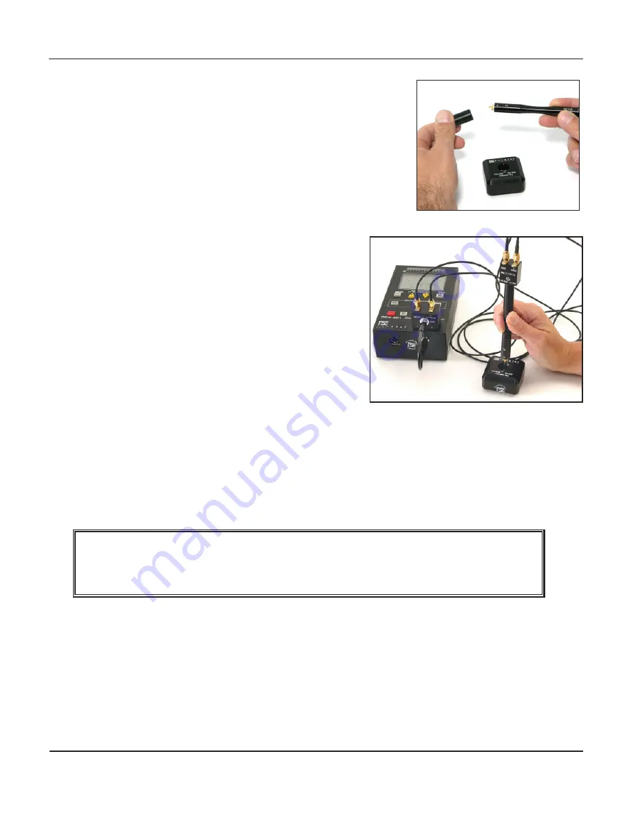
2.  Remove PRF-912B Probe Cover (Figure 8).

3.  Position PRF-914B vertically into the PRV-913B Verifier with 

its spring loaded pin electrodes making direct contact with 

the Verifier’s gold  plated test segments.

4.  Depending on your resistance instrument select either 10V 

or 100V test voltage. 

5.  Measure PRF-914B probe resistance while positioned in the 

PRV-913B Verifier. Resistance should be 1.0x10

6

 ohms ±5%.

D.  Basic Measurements Using the PRF-914B Micro Probe

1.  Place material to be measured on an insulated test 

bed, the clean insulated surface (Black, labeled 

side) of the PTB-920, or an insulated acrylic plate. 

2.  Position the PRF-914B vertically directly over test 

area and lower it until the spring loaded center 

electrode makes direct contact with the material 

under test.

3.  Apply sufficient pressure on the probe until the 

center and outer spring loaded electrode are 

partially compressed while in contact with the test 

material. 

4.  Select appropriate instrument test voltage and 

initiate resistance measurement. ESD Association 

S11.11 test voltage guidelines for measuring pack

-

aging materials are as follows: 

a.  For material resistance measurements of less than 1.0x10

4

 ohms, use <10 volts. 

b.  For measurements of 1.0x10

4

 to <1.0x10

6

 ohms, use 10 volts.

IMPORTANT NOTE


Adjust probe pressure to insure that the electrode springs are controlling the probe’s con

-

nection with the material’s surface and that the springs are not fully compressed against 

their stops. This will insure reproducible measurements.

Figure 9: Remove Probe Cover

Figure 10: Insert PRF-914B Fixture into PRV-

913B Verifier and Measure Verifier Resis

-

tance.

Summary of Contents for PRF-914B

Page 1: ...User Manual PRF 914B MINIATURE CONCENTRIC RING FIXTURE ...

Page 2: ......

Page 3: ...nce 11 V Warranty Information 13 General Specifications 14 Table of Contents Copyright 2012 by Prostat Corporation All rights reserved Printed in the United States of America No part of this manual may be used or reproduced in any manner whatsoever without written permission For information contact Prostat Corporation 1072 Tower Lane Bensenville IL 60106 USA Prostat is the registered trademark of ...

Page 4: ...tely 1 10th the size of the S11 11 fixture Based on its size the PRF 914B is often referred to as a micro probe 1 The resistance measurement range of the PRF 914B fixture is 0 9 ohms at 10 volts to 1 0E 14 1 0x1014 ohms at 100 volts 2 The miniature concentric fixture consists of a spring loaded 0 10 inch 2 54 mm diameter center electrode surrounded by 10 each 0 06 inch 1 5 mm diameter contact elec...

Page 5: ...2B PRF 914B and PRF 922B Microprobe Resistance Fixtures It consists of a high quality black anodized housing and circuit board incor porating an array of ten 10 each 10 megohm precision 2 resistors in parallel connecting the center pad to each of the ten peripheral trace pads it provides a specific reference resis tance of 1 0x106 ohms 5 on the concentric ring side On the other side it consists of...

Page 6: ...formance micro probed designed for use with a maximum input voltage of 100 volts As such it is capable of delivering an annoying shock to any person touch ing the spring loaded contacts when they are energized a If used with the Prostat PRS 801 Resistance System the current capability of the micro probe instrument combination is limited to a very low typically harmless level However a distinct haz...

Page 7: ...tampering or attempted re pair will absolutely void product warranty and completely absolve Prostat Corporation of any responsibility liability or other whatsoever 4 Do Not Touch Electrode Surfaces Electrodes will become contaminated with skin oils and salts and may become damaged or rendered inaccurate 5 Do Not Use Or Store PRF 914B Or PRV 913B In Damp Environments Always store devices with prote...

Page 8: ...e connectors Tighten finger tight only 2 Connect the Sense cable s BNC fitting to the instrument Adapter s Sense terminal 3 Connect the Source cable s BNC to the instrument Adapter s Source terminal Figure 6 4 Once the cables are installed and connected to the Instrument Adapter the PRF 914B is ready for connection to a wide range ohmme ter continuity test verification and use 5 Connect Instrument...

Page 9: ... slightly compress the electrodes mak ing positive contact with the metal surface b Activate the wide range resistance instrument to obtain a measurement In the case where the Prostat PRS 801 is the measurement instrument it should measure approximately 1 0 ohm or less 2 Repeat the above procedure using the clean insulated surface Black labeled side of the PTB 920 or an insulated acrylic plate a H...

Page 10: ... and lower it until the spring loaded center electrode makes direct contact with the material under test 3 Apply sufficient pressure on the probe until the center and outer spring loaded electrode are partially compressed while in contact with the test material 4 Select appropriate instrument test voltage and initiate resistance measurement ESD Association S11 11 test voltage guidelines for measur...

Page 11: ...probe individually by grasping it firmly then pulling it straight out of its socket b Inspect each probe for damage then clean with the alcohol solution If a probe is damaged i e bent does not compress smoothly or has deep surface scratches replace it with a new probe of the same size and characteristics Contact Prostat Corporation Customer Service for spare replacement probes c Clean and dry the ...

Page 12: ... Verification Fixture 1 Store the PRV 913B in a clean dry environment 2 Periodically clean and dry the gold fixture contact segments twice with a solution of laboratory grade isopropyl alcohol and laboratory quality swab Figure 13 View of PRF 912B Spring Loaded Test Pins Socket Teflon Mounting Disk Figure 14 Insert Test Probe into its Socket and Press Firmly to fully seat ...

Page 13: ... not limited to contract negligence or strict liability Fulfillment by Prostat of its express warranty obligations described above will be purchaser s exclusive remedy and will be Prostat s and seller s limit of liability for any breach of warranty or otherwise B Shipping of Warranty Returns 1 Obtain a Return Materials Authorization RMA number and shipping address from Prostat customer service Pac...

Page 14: ...meter Size Probe Spring 3 5 pounds 1 6 kg Force Test Probe Total Travel 0 3 inches 7 8mm Connection BNC with outer source and inner sense connections Cable Dual RG 174 coaxial cables equipped with SMA connectors Instrument Adapter for connection to Prostat PRS 801 Resistance System equipped with BNC male terminals to fit cable BNC female fittings Power Not applicable Fixture powered by resistance ...

Page 15: ...15 Rev A November 2005 PRF 914B High Resistance Miniature Concentric Ring Fixture Set NOTES ...

Page 16: ...16 Rev A November 2005 PRF 914B High Resistance Miniature Concentric Ring Fixture Set NOTES ...

Page 17: ...17 Rev A November 2005 PRF 914B High Resistance Miniature Concentric Ring Fixture Set NOTES ...

Page 18: ...18 Rev A November 2005 PRF 914B High Resistance Miniature Concentric Ring Fixture Set NOTES ...

Page 19: ......

Page 20: ...ville IL 60106 630 238 8883 Fax 630 238 9717 1 855 STATIC1 www prostatcorp com Prostat Corporation Specifications are subject to change without notice All Prostat trademarks and trade names are the property of Prostat Corporation All other trademarks and trade names are the property of their respective companies ...

Reviews: