2. Be sure the wipe excess material from the top of the acrylic frame
B. Fixture Connections
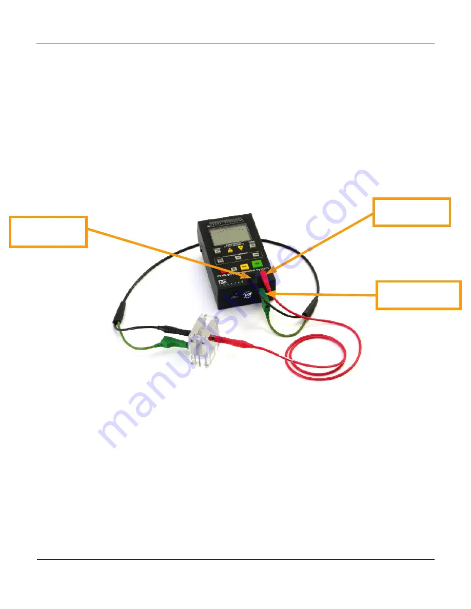
Three connections to a precision, wide range resistance system (Figure 7) are required for accurate
measurements:
1. Connect the instrument’s test voltage (power) lead, usually from the Positive (+) terminal to
the Red connection mounted on the fixture’s power plate.
2. Connect the instrument’s current sensing lead, usually the Negative (-) terminal, to the Black
center plate receptical.
Figure 7: Shielded Lead Set Connections
Negative (-)
Terminal
Instrument Ground
Reference
Positive (+)
Terminal
3. Connect the instrument’s ground reference to the Green guard plate receptical
C. Making the Resistance Measurement
The PRF-930 complies with the fundamental requirements of measuring bulk resistance of pow-
dered and granulated materials. Actual procedures and specified conditions may vary between
test methods cited by standards bodies in different countries. The PRF-930 was designed in accor-
dance with the Recommended Practice for Protection against Hazard arising out of Static Electric-
ity in General Industrie, published by The National Institute of Industrial Safety, Japan, Technical
Recommendation No. RIIS-TR-87-1. Other national committees may be examining similar methods
for these measurements.
Center Plate
Connection
Guard Plate
Connection
Power Plate
Connection
8
Rev. A / January 2010
PRF-930 Advanced Powder Fixture


