93-520-20 Issue 3.3
Page 13 of 60
CirrusPro Engineer’s Manual
2.0 Installation
2.1
Equipment Received
CirrusPro Aspirating Fire Detector Unit
Vacuum Pump (packed separate with some models)
Full Water Bottle (Triple De Ionised Water)
Water Bottle Top with pipe connector
Wall Mounting Template
Allen key (or door keys on 200+, 200DSC, and X4)
Engineer’s Manual (This Manual)
User Manual
2.2
Installation Procedure
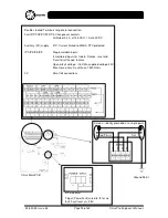
Refer to the connection diagram on the following pages.
1. Remove the wall-mounting template from packing case. Drill 3 holes in wall for relevant unit (4 for
200+, 200DSC, and X4).
2. Prepare the box for the knockouts required for wiring. Ensure that metal filings are removed from
inside the box as these could cause a short circuit. The knockouts should be knocked out rather
than drilled.
3. Do not remove any pipe work ‘bungs’ until ready to fit the pipes.
4. Mount the case on the wall using the three (or four) mounting holes. Ensure unit is level in all
planes.
5. Fit all required wiring glands. Note the position of the power supply terminal block and input/output
terminal blocks to ensure sufficient length of tails are left for easy connection.
6. Clean the inside of the enclosure removing dust or debris.
7. Identify the following connections and cables (see next page):
Power connector
Input output connectors for cables
Expansion PCB (extra outputs on scanning units)
RS485 Network connector
8. Ensure unit is wired correctly for the power, and inputs/outputs required for operation. Do not
connect any power at this time.
9. Ensure all airflow pipes are fully home in the manifold and any unused holes are plugged with the
bungs provided.
10. Remove all packing pieces such as bubble wrap from around the vacuum pump.
11. The unit is now ready to be commissioned.
12. Follow the pre commissioning instructions in Section 3


