93-520-20 Issue 3.3
Page 33 of 60
CirrusPro Engineer’s Manual
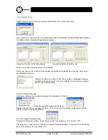
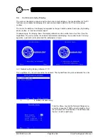
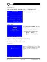
Pressing SEL moves the highlighting to the next editable section.
+
and
–
increment and decrement
the values.
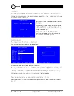
Node Number
128 is the default and can be set in the range 96 to 128. These numbers are for
display units only. 128 should be included and then the numbers should increment down from 128.
The
Connect Node
is the number of the detector unit that the display is linked to. Setting the Connect
Node to 000 allows the display to cycle round detector units. If an event occurs, the display latches
onto that detector unit until reset or cleared.
To assign the display permanently to a detector unit then use the detector network number 255 – 224.
Note that Detector Unit Network numbers cannot be assigned from a display unit, only from a PC.
The number of Displays and the number of Detectors are set up as required. For example the default
setting is for a single detector unit with an integral display and set up as 128,255,01,01.
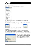
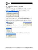
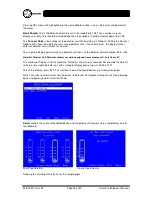
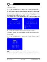
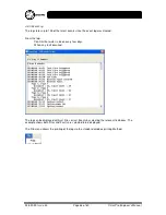
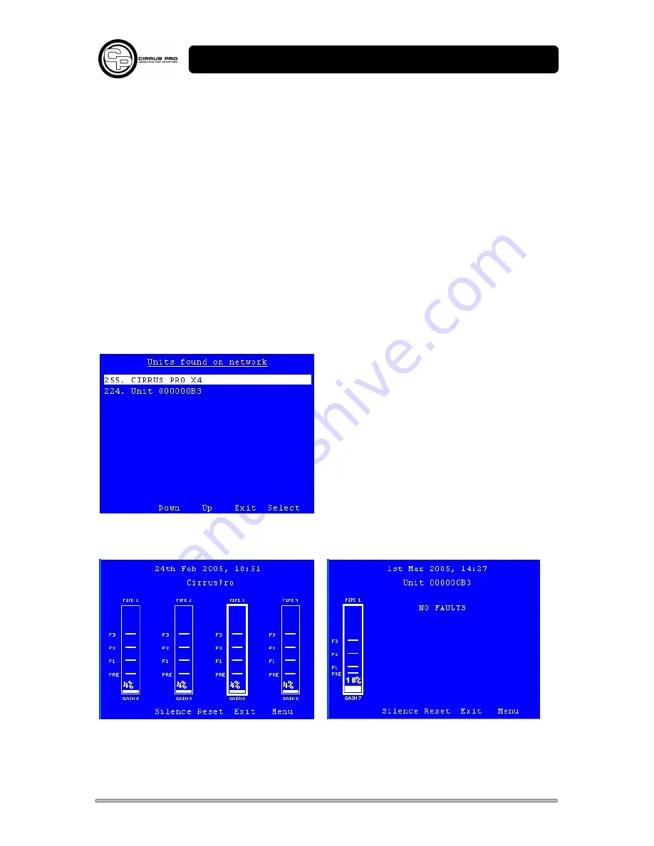
To exit this display, press Exit. This will then show all the found devices e.g two devices below:
Note It can take several minutes for all devices to be found. To improve finding of units then powering
down and powering up of all units will help.
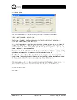
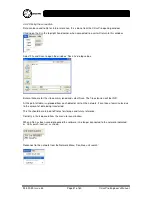
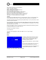
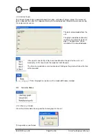
Select
accepts the current highlighted device and the display unit request status and displays one of
the following:
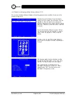
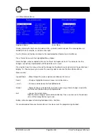
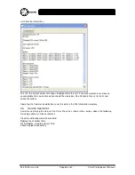
Four Pipe Detector
Single Pipe Detector
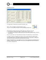
Showing the current particle levels for the sample pipes.

