93-520-20 Issue 3.3
Page 40 of 60
CirrusPro Engineer’s Manual
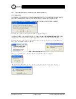
Inputs are be configured as one of the following:
Unused – The input is ignored
Isolate – Alarm relays are Isolated
Reset – Reset the sensor from any latched state
Disable – Shut down the CirrusPro
Fault – External Fault input that indicates as External Fault
Gain set – Uses all 4 inputs to set the gain of the unit
Battery Fault – External Fault input that indicates as Battery Fault
Mains Fault – External Fault input that indicates as Mains Fault
S/R Disable – The Silence and Reset keys are disabled
Outputs
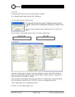
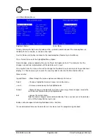
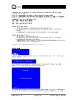
Four outputs are available within each unit. On scanning systems, there is a set of 4 per pipe. These
are non-monitored, volt free contacts. The pipe number can be selected on a scanning system.
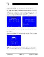
The outputs will switch at the required alarm level. By default Output 1 to 4 are set to Pre-Fire, Alarm1,
Alarm2 and Alarm3 respectively.
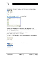
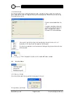
By entering a Delay value greater than zero, the output is delayed, once the level has been reached,
for the specified time. The example shows a 20 second delay before activating output 1 when the pre
alarm threshold has been reached.
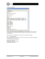
Each of these outputs can be set as Normally Open (default) or Normally Closed. Normally Closed is
selected by highlighting the N.O and pr or –.
Selecting ‘Unused’ disables the output.
3.4.12 Output Test
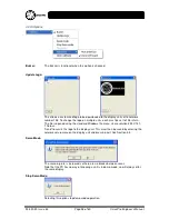
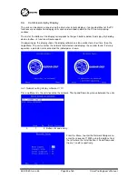
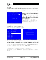
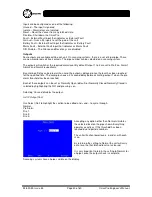
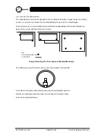
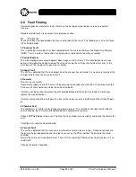
Use Select (Sel) to highlight the section to be edited and + and – to cycle through :
Normal,
Pre Alarm,
Fire 1,
Fire 2,
Fire 3.
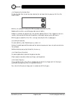
Accepting any option other than Normal simulates
the selected level on the pipe shown. Everything
operates exactly as if this threshold has been
reached due to particle numbers.
The unit will action lower levels, in order, with each
scan.
By returning the setting to Normal the unit will carry
out a reset so that latched levels are cleared.
It is very important to return the setting to Normal for
all pipes once the output check is complete.
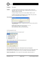
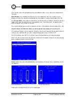
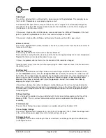
Scanning systems have all pipes visible on the display.

