background image

Safety Warnings and Precautions

WARNING: When using tool, basic safety precautions should always be followed to reduce the risk of
personal injury and damage to equipment.

1. Keep work area clean.

Cluttered areas invite injuries.

2. Observe work area conditions.

Do not use machines or power tools in damp or wet locations. Don’t

expose to rain. Keep work area well lighted. Do not use electrically powered tools in the presence of
flammable gases or liquids.

3. Keep children away.

Children must never be allowed in the work area. Do not let them handle

machines, tools or extension cords.

4. Store idle equipment.

When not in use, tools must be stored in a dry location to inhibit rust. Always

lock up tools and keep out of reach of children.

5. Avoid Unintentional Starting

. Be sure the air pressure is in the off position when not in use and before

making hose connection.

6. Stay alert

. Watch what you are doing, use common sense. Do not operate any tool when you are tired.

7. Check for damaged parts

. Before using any tool, any part that appears damaged should be carefully

checked to determine that it would operate properly and perform its intended function. Check for
alignment and binding of moving parts; any broken parts or mounting fixtures; and any other condition
that may affect proper operation. Any part that is damaged should be properly repaired or replaced by a
qualified technician. Do not use the tool if any control or switch does not operate properly.

8. Replacement parts and accessories.

When servicing, use only identical replacement parts. Use of any

other parts will void the warranty. Only use accessories intended for use with this tool.

9. Do not operate tool if under the influence of alcohol or drugs.

Read warning labels if taking

prescription medicine to determine if your judgment or reflexes are impaired while taking drugs. If there
is any doubt, do not operate the tool.

10. Maintenance.

For your safety, service and maintenance should be performed regularly by a qualified

technician.

Note: Performance of this tool may vary depending on variations in air pressure and compressor
capacity.

Summary of Contents for HC-2297

Page 1: ......

Page 2: ...you are tired 7 Check for damaged parts Before using any tool any part that appears damaged should be carefully checked to determine that it would operate properly and perform its intended function Check for alignment and binding of moving parts any broken parts or mounting fixtures and any other condition that may affect proper operation Any part that is damaged should be properly repaired or rep...

Page 3: ... recommended operating air pressure This could damage equipment See specification on Page 5 7 Keep a type ABC fire extinguisher nearby in case of fires 8 Always protect your skin and eyes from contact with oil and solvents 9 Do not start engine during the time of oil extraction Otherwise it will cause the damage of extraction probes and injuries of people 10 Be careful for the oil extracted out fr...

Page 4: ...d robust CU probe Power from compressed air Air Inlet Pressure 6 8bar 87 116PSI Ejection pressure 0 7 1bar 10 15PSI Air Consumption 150L Min Vacuum Degree 0 1 bar 15PSI Tank Capacity 80L Cylinder Capacity 9L Oil tray volume 15L Working Temperature 40 60 Package Cylinder box oil tank box Carton size 270 270 525mm 550 430 980mm Suction probes Φ5 L700mm Cu 1 PCS Suction speed 1 9 L Min Φ6 L700mm Cu 1...

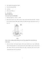
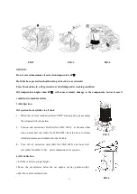
Page 5: ...extraction When finger reaching to the MAX area on the vacuum gauge turn off air inlet valve FIG 1 Notice Under a working condition without air source Please pump with vacuum air before use 2 Extraction 1 Ensure the oil tank is under negative pressure FIG 2 remove engine oil case choose suitable probe which is the largest diameter one can be inserted into the engine and tightly connect it to the e...

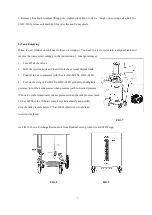
Page 6: ...en the oil level reached cylinder STOP warning line please empty the cylinder with oil ejection 2 Turn on ball extraction valve Part No 32HC 1005 at the same time turn on mini ball valve Part No 32HC 0803 from the hose to release cylinder pressure and oil drain into the oil tank 3 Turn off oil extraction valve Part No 32HC 1005 and hose ball valve Part No 32HC 1703 after completion of oil ejection...

Page 7: ...d the ejection hook and insert it into the external disposal tank 3 Connect the air compressor with the air inlet Part No 32HC 0801 4 Turn on the wing valve Part No 32HC 0402 gradually addingtank pressure turn off air compressor when pressure reach to desired pressure The valve will automatically release pressure when the tank pressure reach 1 0 bar 14PSI turn off the air compressor immediately an...

Page 8: ...8 ...

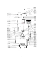
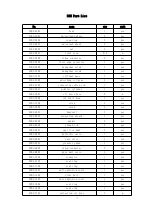
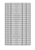
Page 9: ... 21HC 1801 oil drain hose 2 m 21HC 1802 oil drain hook 1 pcs 21HC 1902 screw 2 pcs 21HC 2003 screw 2 pcs 21HC 2801 handrail 1 pcs 21HC 2802 protection sheath 1 pcs 32HC 0303 gasket 4 pcs 32HC 0304 thread rod 2 pcs 32HC 0401 cast iron bend 3 pcs 32HC 0402 butterfly valve 1 pcs 32HC 0601 safe valve 1 pcs 32HC 0701 pressure gauge 1 pcs 32HC 0802 elbow connector 2 pcs 32HC 0803 mini ball valve 1 pcs 3...

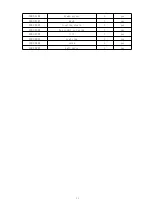
Page 10: ... 1 pcs 32HC 2703 handle sleeve 2 pcs 20HC 1501 vacuum gauge 1 pcs 20HC 1507 Y connector 1 pcs 32HC 0801 wind nozzle 2 pcs 32HC 1101 Bolt 1 pcs 32HC 1102 vacuum generator 1 pcs 32HC 1103 silencer 1 pcs 32HC 1107 seal ring 1 pcs 32HC 1201 bead valve 1 set 32HC 1502 connector 1 pcs 32HC 1503 hollow bolt 1 pcs 32HC 1504 seal ring 1 pcs 32HC 1505 rubber gasket pcs 32HC 1506 metallic gasket 1 pcs 32HC 1...

Page 11: ...2104 brake sleeve 1 pcs 32HC 2107 knob 1 pcs 22HC 4303 locating sleeve 1 pcs 22HC 4304 hex socket set screw 1 pcs 22HC 4307 lift 1 pcs 21HC 3805 seal ring 1 pcs 21HC 3806 screw 1 pcs 21HC 3807 ball valve 1 pcs ...

Reviews: