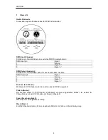
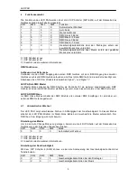
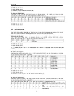
background image


Bedienungsanleitung /  

User Manual 


PAR 36 RGB LED MKII 
PAR 56 RGB LED MKII 
PAR 64 RGB LED MKII 

PAR 64 RGB LED 24x1W 


mit DMX Ein- und Ausgang/ 

with DMX In- and Output 


Summary of Contents for PAR 36 RGB LED MKII

Page 1: ...Bedienungsanleitung User Manual PAR 36 RGB LED MKII PAR 56 RGB LED MKII PAR 64 RGB LED MKII PAR 64 RGB LED 24x1W mit DMX Ein und Ausgang with DMX In and Output...

Page 2: ...MX Master 5 Kanal Modus 9 4 6 DMX Slave 3 Kanal Modus 12 4 7 DMX Master 3 Kanal Modus 13 5 Technische Daten 14 Content 6 Safety Instructions 15 7 Introduction 15 8 Overview 15 9 Function Selection 16...

Page 3: ...r andere Teile w hrend das Ger t in Betrieb ist Spannungsf hrende Teile k nnen zu lebensgef hrlichen Stromschl gen f hren Das Geh use darf w hrend des Betriebs nicht mit blo en H nden ber hrt werden B...

Page 4: ...as n chste DMX Ger t an DMX Output pin Signal 1 Erdung 2 Signal 3 Signal Function Funktionen Mit diesen 4 DIP Schaltern wird die Funktion des LED PAR eingestellt Pattern Muster Die Funktion dieser 10...

Page 5: ...aster Im Master Modus arbeitet der DMX Strahler als Kontroller f r die weiteren angeschlossenen DMX Strahler Wird der LED PAR Strahler als Master genutzt muss dieser der erste in der DMX Kette sein LE...

Page 6: ...chalter ist an X in diesem Modus kann die Geschwindigkeit nicht ber den Drehregler oder die Musik gesteuert werden Fade Geschwindigkeit Die Fade Geschwindigkeit wird ber die 10 DIP Schalter SW1 SW10 a...

Page 7: ...igkeit nicht ber den Drehregler oder die Musik gesteuert werden Farbmuster Einstellung Rote Farbe Die Rote Farbe wird ber 10 DIP Schalter SW1 SW10 auf der R ckseite des Ger tes anhand der folgenden Ta...

Page 8: ...Kan le angesteuert Mit den DIP Schaltern 1 bis 9 wird der erste DMX Kanal auf Empfang gesetzt Einstellen des Modus Um in den 5 Kanal DMX Slave Modus zu gelangen ndern sie die 4 DIP Schalter SW1 SW4 a...

Page 9: ...ein Bin r Code Um den gew nschten DMX Empfangskanal einzustellen m ssen sie die DIP Schalter SW1 SW10 wie in der folgenden Tabelle setzen SW1 SW2 SW3 SW4 SW5 SW6 SW7 SW8 SW9 SW10 Erster DMX Empfangsk...

Page 10: ...ungen im 5 Kanal Betrieb Der LED PAR im Master Modus sendet die DMX Daten wie in der folgenden Tabelle beschrieben Der angeschlossene Slave muss eingestellt sein wie in Kapitel 4 4 beschrieben 1 DMX K...

Page 11: ...0 0 0 0 4 Kanal Muster 3 alle an alle machen das Selbe mit Fade in und Fade out 1 0 0 1 0 0 0 0 0 0 4 Kanal Muster 1 alle an jeder LED PAR hat eine andere Farbe mit Fade in und Fade out 0 1 0 1 0 0 0...

Page 12: ...0 0 0 0 0 Chaser Muster 2 rechts nach links links nach rechts neue Farbe pro Schritt 0 0 1 1 1 0 0 0 0 0 Chaser Muster 3 rechts nach links neue Farbe pro Schritt 1 0 1 1 1 0 0 0 0 0 Chaser Muster 3 r...

Page 13: ...0 0 0 0 0 0 0 1 0 256 0 DIP Schalter ist aus 1 DIP Schalter ist an Anmerkung Wenn alle Schalter auf Null stehen ist der erste DMX Empfangskanal 1 Falls nur der Schalter 1 an ist ist der erste DMX Empf...

Page 14: ...R N 3 DMX Kanal BLAU 9 DMX Kanal BLAU 4 DMX Kanal ROT 10 DMX Kanal ROT 5 DMX Kanal GR N 11 DMX Kanal GR N 6 DMX Kanal BLAU 12 DMX Kanal BLAU Einstellung der Farbmuster Hier gelten die Selben Einstellu...

Page 15: ...ent patterns available e g all connected LED PARs do the same each shows different patterns chaser programs fade in fade out patterns and fade over patterns The steps of the patterns can be controlled...

Page 16: ...meter if selected mode support it X X X 1 speed control by music if selected mode support it 0 dipswitch is set to off 1 dipswitch is set to on X see information below above 9 1 Auto change mode The L...

Page 17: ...e 10pin dipswitch on the backside of the LED PAR according to this table SW1 SW2 SW3 SW4 SW5 SW6 SW7 SW8 SW9 SW10 Fading speed selection 0 0 0 0 X X X 0 0 0 10 30min 1 0 0 0 X X X 0 0 0 2 5s 0 1 0 0 X...

Page 18: ...X X X X X 0 85 1 1 1 X X X X X X 0 100 0 dipswitch is set to off 1 dipswitch is set to on X see table below The green colour may be set by the 10pin dipswitch on the backside of the LED PAR according...

Page 19: ...PAR by an external DMX controller Channel 1 value Function 0 63 RGB control CH2 red CH3 green CH4 blue 64 127 7 colour fade CH5 speed control 128 191 7 colour change CH5 speed control 192 255 3 colour...

Page 20: ...ble SW1 SW2 SW3 SW4 mode 0 0 1 X DMX master 5ch 0 dipswitch is set to off 1 dipswitch is set to on X see information below Speed setting SW4 setup the speed source Choose the speed source according th...

Page 21: ...e in and out 1 1 1 0 0 0 0 0 0 0 4ch Pattern 2 all on all do the same with fade in and out 0 0 0 1 0 0 0 0 0 0 4ch Pattern 3 all on all do the same with fade in and out 1 0 0 1 0 0 0 0 0 0 4ch Pattern...

Page 22: ...lour each step 0 dipswitch is set to off 1 dipswitch is set to on Two LED PAR of four is on SW1 SW2 SW3 SW4 SW5 SW6 SW7 SW8 SW9 SW10 Colour pattern selection 0 1 1 1 1 0 0 0 0 0 chaser pattern 1 right...

Page 23: ...osen first receive channel bigger than 510 the maximum receive channel is still 510 9 7 DMX master 3ch mode This mode has the same functions as the DMX master 5ch mode chapter 9 The difference is the...

Page 24: ...er 5ch mode see 9 5 10 Technical Specifications LED PAR 36 MKII Number of LEDs 61 LEDs 5mm Power supply 230V 50 Hz Power consumption Max 9W Dimensions 107 x 107 x 176 mm Weight 0 85 kg LED PAR 56 MKII...

Reviews: