Chapter 3 Hardware Configuration
PA-3222 SERIES USER MANUAL
Page: 3-13
3.6.2
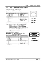
COM Connectors (COM1_1, COM2_1, COM3_1, COM4_1)
Connector Name:
COM1_1, COM2_1, COM3_1, COM4_1
Description:
COM Connectors
PIN ASSIGNMENT
PIN ASSIGNMENT
1
DCD
6
DSR
2
RXD
7
RTS
3
TXD
8
CTS
4
DTR
9
RI/+5V/+12V selectable
(Max. current: 1A)
5
GND
10
NC
3.6.3
i-Button Connector (I-BUT)
Connector Name:
I-BUT
Description:
i-Button Connector
PIN ASSIGNMENT
1
COM3_DTR_R_I
2
COM3_RXD_R_I
3.6.4
COM2 & i-Button Function Selection (JP10, JP11, JP12)
Jumper Name:
JP10, JP11, JP12
Description:
i-Button Function Selection
SELECTION JUMPER SETTING
JUMPER ILLUSTRATION
COM2
1-2
(Default Setting)
JP10/JP11/JP12/
I-BUT*
2-3
JP10/JP11/JP12/
*COM2 & COM2_1 will not function when jumpers JP10, JP11 & JP12 are set as
“I-BUT”.
I-BUT
COM1_1/
COM2_1/
COM3_1/
COM4_1
/
1
6
5
10
Summary of Contents for PA-3222
Page 1: ...USER MANUAL PA 3222 10 1 POS Terminal Powered by Intel Celeron J1900 Quad Core PA 3222 M1...
Page 11: ...viii Configuring WatchDog Timer B 10 Flash BIOS Update B 13...
Page 24: ...Chapter 2 Getting Started PA 3222 SERIES USER MANUAL Page 2 10 2 3 6 Side View 147 75...
Page 26: ...Chapter 2 Getting Started PA 3222 SERIES USER MANUAL Page 2 12 2 4 3 Top View...
Page 163: ...Chapter 4 Software Utilities PA 3222 SERIES USER MANUAL Page 4 78...
Page 221: ...Appendix A System Diagrams PA 3222 SERIES USER MANUAL Page A 4...
Page 247: ...Appendix B Technical Summary PA 3222 SERIES USER MANUAL Page B 14...


