Katana S180 - 11
Installing the engine / Monteren van de motor /
Installation du moteur / Montieren von Motor
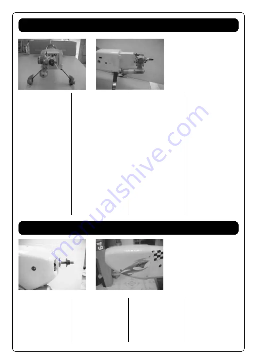
fig. 22
fig. 23
We recommend that you install
the most 2T engines in 90
°
or
45
°
.
Install the engine to the engine
mount and lock with four
M5x25mm screws and lock nut.
Put the engine on the fire wall
and mark the holes. Drill four
holes in the fire wall and install
four blind nuts on the backside
of the fire wall. Install the engine
mount with four M4x20mm
screws.
The engine thrust line is 50mm
down from the top of the engine
box.
The sidethrust is 2
°
and the
back side of the engine should
be above 5mm from the center
line.
The engine drive hub distance
from the fire wall is 146mm.
Glue four supports to fix the
motor cowling.
See fig. 22-23.
Wij raden voor de meeste 2T
motoren aan dat u ze in een
hoek van 90
°
of 45
°
monteert.
Schroef de motor op de
motorsteun met vier M5x25mm
vijzen en verlijm met lock nut.
Plaats de motor op de
vuurspant en duidt aan waar de
gaatjes moeten komen. Boor
vier gaatjes in de vuurspant en
plaats vier moeren in de
motorsteun. Bevestig de motor
met vier M4x20mm vijzen. De
thrust-lijn van de motor zit op
50mm van de bovenkant van de
motorsteun. De rechtse thrust is
2
°
van de achterzijde van de
motor moet op 5mm boven de
centerlijn staan. De afstand van
de motoraandrijving is 146mm.
Verlijm vier bevestigingsplaatjes
op de vuurspant voor het
monteren van de motorkap.
Zie fig. 22-23.
Nous recommandons l’installa-
tion des moteurs 2T à 45
°
ou
90
°
.
Fixez le moteur sur le bâti avec
les vis M5x25mm et écrous
nylstop. Positionnez le moteur
sur le couple “anti-feu“ et
marquez les trous. Percez les 4
trous dans la paroi et installez
les 4 écrous à griffes sur la paroi
“anti-feu“ par l’intérieur du
fuselage. Fixez le bâti avec 4 vis
M4x20mm.
L’axe longitudinal du moteur se
trouve à 50mm par rapport au-
dessus de la paroi “anti-feu“.
Nous recommandons un angle
2
°
pour l’anticouple et de
décaler l’arrière du moteur de
5mm vers le haut par rapport
l’axe longitudinal afin de donner
un léger effet de “piqueur“.
Le plateau d’hélice doit se
trouver à 146mm de la paroi
“anti-feu“.
Collez les 4 supports pour fixer
le capot moteur.
Voir fig. 22-23.
Installing the motorcowling / Bevestigen van de motorkap /
Installation du capot moteur / Montieren von Motorhaube
fig. 24
fig. 25
Drill out the air intake on the
cowl and smoothen it with a file
or sanding paper, see fig. 24-25.
Make sure the engine drive hub
has a spacing of at least 3-5mm
with the cowl end.
Screw the cowling in place.
Boor de luchtinlaat uit en schuur
of vijl de randen glad, zie fig. 24-
25.
Zorg ervoor dat de
motoraandrijving ten minste 3-
5mm spatie heeft t.o.v. het
voorste van de motorkap.
Vijs de motorkap op zijn plaats.
Percez le contour des prises
d’air dans le capot, enlevez-les
délicatement et ajustez à la lime
ou papier abrasif, voir fig. 24-25.
Assurez-vous de laisser un
espace de 3 à 5mm entre le
capot et le plateau d’hélice.
Vissez le capot sur le fuselage.


