background image

SENSOR SETTINGS

(Record Final Sensor Settings Below)

Model No:______________________________

Serial No:_______________________________

Lens Module:____________________________

Circle Sensor Settings

Sensitivity Setting:

(Min.)

  1  2  3  4  5  6  7  8  9  10  

(Max.)

Range Setting: 

10  20  30 40  50  60  70  80  90  100 

(% of Max.)

Bird/Animal Immunity Switch Setting:

[Standard]    [Enhanced]

TABLE OF CONTENTS


     Page

Photo of Printed Circuit Board

Walk Test LED Explanation

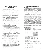
Quick Installation Reference  


A Basic Description   


Specifications   


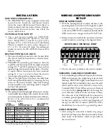
Installation


   Mounting PIRAMID XL2 

   Universal Pole Mount

   Best Mounting Location

   Mounting Height

Wiring & Preliminary Set-Up

   Minimum Wire Size

   Removable Terminal Strip Diagram

   Shielded Cable Recommended

   Cable Holders

   Tamper Switch

   Stabilization Time

   LED On/Off Switch

   Voltage OK LED

Walk Testing

   Analytic Walk Test LED’S

   XL-Sounder Audible Tester

   Helpful Hints for Walk Testing

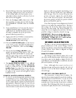
Sensor Adjustments

   Range Control Switch

   Sensitivity Control Switch

   Sensitivity Control Settings Table

   Enhanced Bird/Animal Immunity Switch

Walk Testing Procedure


For Analytic Walk Test LED’S

   For XL-Sounder Audible Tester

Application Guidelines

 - 

DO’S AND DON’TS

   Use as a motion sensor

   Choose a solid mounting base

   Beware of garbage attracting animals

   Avoid Spinning Fan Blades

   Beware of birds perching

   Beware of animal entry through fence

   Beware of animals in the protected area

   Avoid mounting under the eaves of a roof

   Beware of vehicles outside the protected area

Installation Check List

Troubleshooting

15-16

Rear Cover

1
2
2
3
3
3
3
3
4
4
4
4
4
5
5
5
5
5
5
5

5-6

6
6
6
7

7-8

8
8

8-9

10-24

10

11

12

13-14

17-18

19-20

21-22

23-24

25-26

27

28

Summary of Contents for PIRAMID XL2

Page 1: ...cond Sensor is in Alarm Master Alarm RED LED is ON because Passive Infrared Alarm RED LED and Microwave Alarm YELLOW LED are ON simultaneously Optional XL Sounder sounds a continuous tone PIR ECI LED...

Page 2: ...rs Tamper Switch Stabilization Time LED On O Switch Voltage OK LED Walk Testing Analytic Walk Test LED S XL Sounder Audible Tester Helpful Hints for Walk Testing Sensor Adjustments Range Control Switc...

Page 3: ...ft x 9 ft 30m x 3m Changing the Lens Module see inside back cover Pet Alley Lens Modules Lens A Pet Wide Angle Lens B Pet Medium Angle Lens C Pet Narrow Angle Note SDI 77XL2 is equipped from the fact...

Page 4: ...NS MODULE LENS DESCRIPTION MOUNTING HEIGHT Sensor Mounting Height Based On Lens Module Selection 3 WIRING AND PRELIMINARY SET UP MINIMUM WIRE SIZE 1 With the housing shroud assembly attached to the mo...

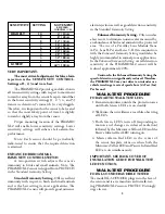
Page 5: ...umb is to set at the lowest setting to attain the desired range SENSITIVITY CONTROL SWITCH The Sensitivity Control Switch adjusts the amount of movement required for an alarm condition The Sensitivity...

Page 6: ...ALK TEST PROCEDURE FOR ANALYTIC WALK TEST LED s 1 Remain motionless outside the protection area until both Green LED s are on steadily 2 Walk into the surveillance area while observing all LED s 3 Bot...

Page 7: ...a fast beep at a rate of approximately 8 beeps per second The fast beep will continue only while the microwave sensor portion remains in alarm The fast beep will stop when the microwave portion resets...

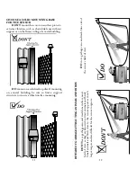
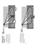
Page 8: ...ation such as chain link fence without support or on the imsy siding of a metal building 11 BEWARE OF GARBAGE ATTRACTING ANIMALS AND BIRDS 12 DON T leave garbage cans and trash bins in the sensor s el...

Page 9: ...WARE OF FAN BLADES IN THE SENSOR S FIELD OF VIEW DON T aim the sensor at moving fan blades as the movement of the blades may cause false alarms 14 DO DO aim and or mount the sensor to avoid looking at...

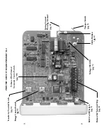
Page 10: ...h pg 6 LED On O Switch pg 5 Removable Terminal Strip pg 4 PRINTED CIRCUIT BOARD PIRAMID XL2 Enhanced Bird Animal Immunity Control Switch pg 7 8 Tamper Switch pg 5 Voltage OK LED pg 5 Range Control Swi...

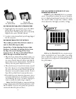
Page 11: ...of view without obstructions 18 BEWARE OF BIRDS PERCHING IN THE SENSOR S FIELD OF VIEW DON T mount the sensor where lighting xtures signs or building structures that can serve as a perch for birds or...

Page 12: ...the fence or gate areas that can serve as easy entry for animals dogs cats raccoons etc into the protected area 20 DO patch holes and secure the fence so animals do not have free access into the prot...

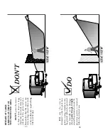
Page 13: ...1 9m Note Pet alley lens modules do not have infrared protection zones that contact the ground 21 BEWARE OF ANIMALS IN THE PROTECTED AREA DON T mount the sensor too low on the wall if animals will be...

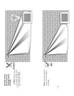
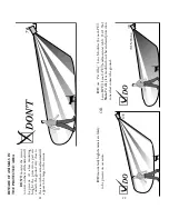
Page 14: ...g of a non guttered roof During heavy rains the runo directly in front of the sensor s face can create nuisance alarms 24 DO mount the sensor where the sensor s weather shroud can route the rain away...

Page 15: ...16 kph around the perimeter to ensure the protection pattern is contained within the protected area 25 BEWARE OF LARGE OBJECTS OUTSIDE OF THE PROTECTED AREA DON T point the sensor so that it may dete...

Page 16: ...r higher so that a small animal cat rat rabbit bird etc on the ground is too small to detect Or have you considered using Pet Alley Lens Modules and mounting lower 4 6 ft Note If all of the above has...

Page 17: ...Changing The Lens Module NOTES 1 2 3...

Reviews: