Chapter 2 Hardware Configuration
Prox-1550 USER
’
S MANUAL
Page: 2-29
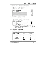
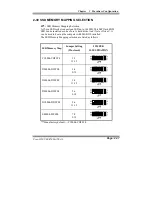
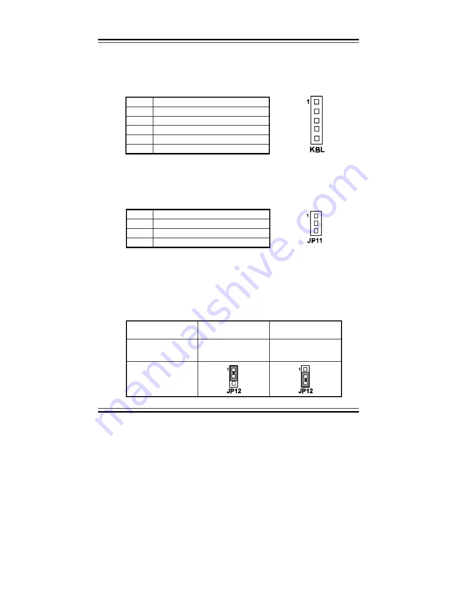
2-19 POWER LED & KEYLOCK CONNECTOR
KBL :
Power LED & Keylock Connector
The pin assignments is as follows:
PIN
ASSIGNMENT
1
Power LED
2
NC
3
Ground
4
Keyboard INT
5
Ground
2-20 PANEL POWER CONNECTOR
JP11 :
Panel Power Connector
This connector is to supply proper power to panel LCD.
The pin assignments is as follows:
PIN
ASSIGNMENT
1
LCD +12V
2
GND
3
LCD VDD (+5V/3.3V)
"
Note: Before using this connector, make sure that you set the JP12
jumper at the same time. Pin #3 can be +5V or +3.3V depending
on the jumper set on JP12.
2-21 PANEL VCC SELECTION
JP12 :
Panel VCC Connector
The pin assignments is as follows:
Panel VCC Selection
VCC
VCC3.3V
JUMPER SETTING
(pin closed)
1-2
2-3
JUMPER
ILLUSTRATION
Summary of Contents for ProX-1550
Page 1: ...USER S MANUAL ...
Page 60: ...Chapter 3 Software Configuration Prox 1550 USER S MANUAL Page 3 11 ...
Page 64: ...Chapter 4 Green PC Function Page 4 4 Prox 1550 USER S MANUAL ...
Page 92: ...Chapter 5 Award BIOS Setup Page 5 28 Prox 1550 USER S MANUAL ...
Page 98: ...Appendix B Technical Summary Page B 2 Prox 1550 USER S MANUAL BLOCK DIAGRAM ...

