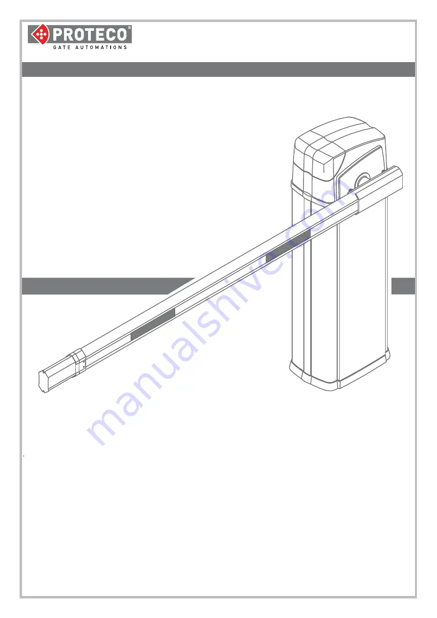
background image

AUTOMATIC ROAD BARRIER  

BARRY

User Manual 

02_18

Summary of Contents for BARRY

Page 1: ...AUTOMATIC ROAD BARRIER BARRY User Manual 02_18...

Page 2: ......

Page 3: ...ATION p 03 5 LOCK AND UNLOCK THE TOP COVER p 03 6 BALANCING OF THE BOOM p 04 7 LIMIT SWITCHES p 05 8 MAIN POWER p 05 9 AC WIRING DIAGRAM 230 115Vac p 06 10 DC WIRING DIAGRAM 24V DC p 08 11 ADDITIONAL...

Page 4: ...ho will be held to check risks and ensure the system complies with the current regulations This product has been designed only for its intended use Any other use could affect the integrity and safety...

Page 5: ...g screws Do not forget wirings While preparing the concrete basement keep a duct of the right dimension to connect the main power and any additional devices if needed 3 3 Fixing the barrier on ground...

Page 6: ...l operation can not be done if the boom is fully raised 5 LOCK AND UNLOCK THE TOP COVER 4 MANUAL OPERATION Remove the top cover if adjustments are needed The cover is secured on the right by a fixed j...

Page 7: ...om may get down therefore proceed to fit both springs Look at the below table to fit correctly the springs according to the boom length Boom length Springs Dimension 3 4 m 1 5 0 x 440 mm 4 5 5 m 2 4 5...

Page 8: ...MAIN POWER 230V GROUNDING The barrier can be powered both 230V and 115V AC and main power has to be wired as shown in the below picture LH BARRIER control unit positioned on the left RH BARRIER contr...

Page 9: ...dge Photocell CLOSE N C GND Common STOP push button N C 12V dc 8W max START STOP Close Open LED WORK LED WARNINGS FACTORY WIRING WIRING BY THE INSTALLER 1 Transformer 2 F1 fuse 0 2 A 3 F2 fuse 5 A 4 V...

Page 10: ...can be adjusted between 1 and 60 seconds DIP SWITCHES DIP switch 1 ON Set dip switch 1 to ON if you need to wire a safety edge the safety edge shall be wired as well on terminal PT on the control unit...

Page 11: ...osing 5 DIP switch 6 Aerial 7 Radio receiver 8 LEARN transmitter storage 9 Start commands 10 Lights and blinker disconnector FACTORY WIRING WIRING BY THE INSTALLER The control unit comes from factory...

Page 12: ...mer clockwise the force increases while the obstacle detection decreases Calibrate the obstacle detection force properly to avoid faults during normal operation We recommend to start setting the force...

Page 13: ...g position If a car crosses through during opening the barrier keeps on to opening position TERMINAL J5 JP5 RF40 RX 1 2 3 C N C N O TX Jumper 0V 24V 28 16 15 25 s h r 5 oo VEK M1H This power supply on...

Page 14: ...ave been deleted TERMINAL J5 JP5 Pulsante apri chiudi N A Pulsante chiusura N A Pulsante apertura N A Pulsante stop N C Power 8W max 12Vdc version 230V 24Vdc version 24V LOOP DETECTOR CONTACT N O 11 3...

Page 15: ......

Page 16: ...Proteco S r l Via Neive 77 12050 CASTAGNITO CN ITALY Tel 39 0173 210111 Fax 39 0173 210199 info proteco net www proteco net...

Reviews: