


7
VR1
VR2
S1
OL CL PT LOOP POWER
LEARN
OPEN STOP CLOSE
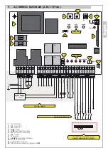
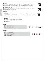
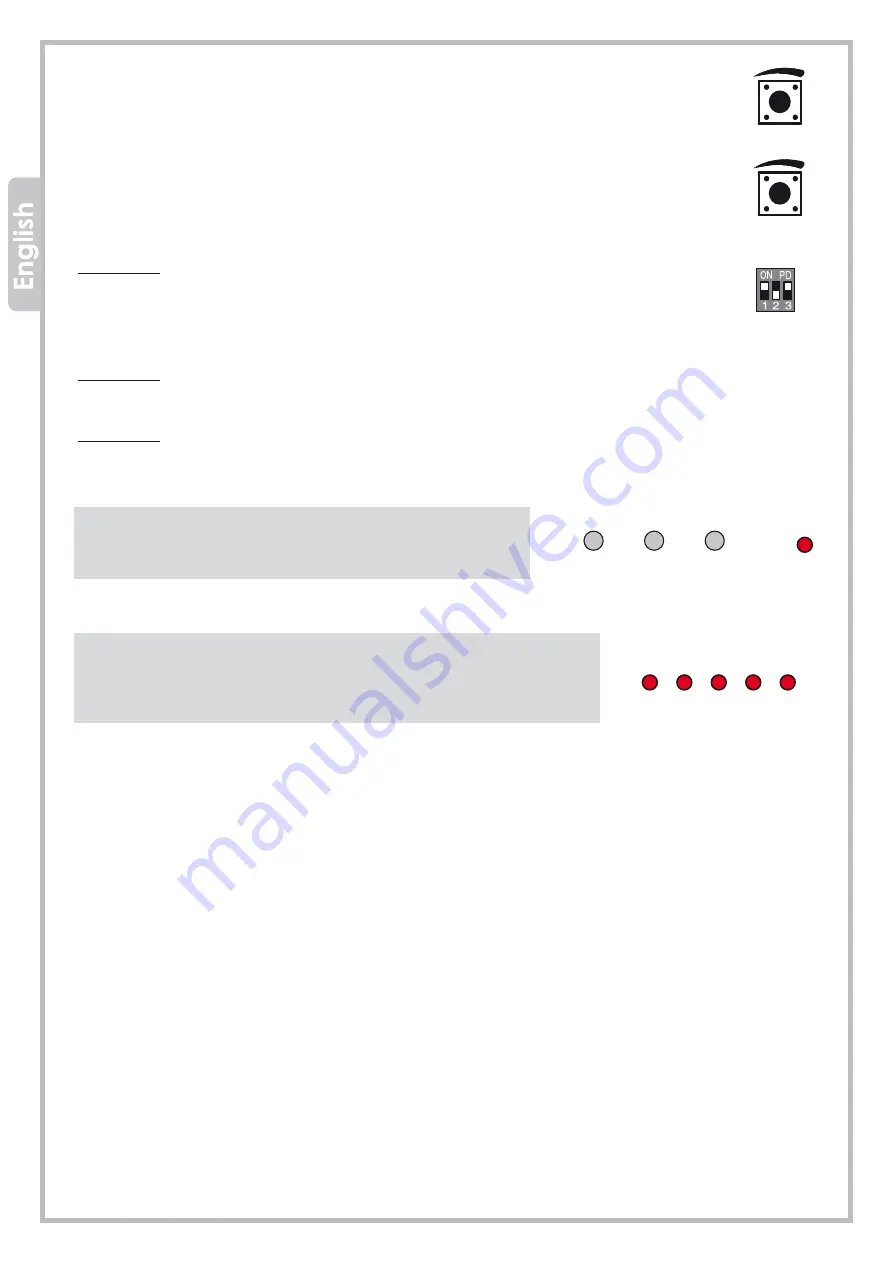
VR1 - FORCE
VR1 trimmer
sets the force and the obstacle detection. Turning the trimmer clockwise the force
increases while the obstacle detection decreases. If J9 jumper is set right side (ON), the obstacle
detection will stop the barrier during closing and will reverse to opening position. Calibrate the
obstacle detection force properly, to avoid faults during normal operation.
VR2 – AUTOMATIC CLOSING
VR2 trimmer sets the automatic closing time (DIP-switch 2 = ON). The automatic closing time can
be adjusted between 1 and 60 seconds.
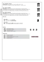
DIP
-
SWITCHES
DIP-switch 1:
ON -
Set dip-switch 1 to ON if you need to wire a safety edge (the safety edge shall be wired
as well on terminal
PT
on the control unit).
OFF
– Set dip-switch 1 to OFF if you need to wire a loop detector (the loop detector shall be
wired as well on terminal
PT
on the control unit).
DIP-switch 2:
ON -
Automatic closing
ACTIVATED
(from 1 to 60 seconds.
OFF -
Automatic closing
DEACTIVATED
.
DIP-switch 3:
Void
LED Work
OPEN
STOP
CLOSE
LEARN
The barrier is opening
The barrier is in stand-by
The barrier is closing
Transmitter storage in progress
LED Warnings
OL
CL
Opening completed
Closing completed
PT
LOOP
Safety edge
/
loop detector operating
Photocells calibrated
POWER
Barrier powered


