Page 17
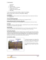
Gate Control Board Connection Terminals (continued):
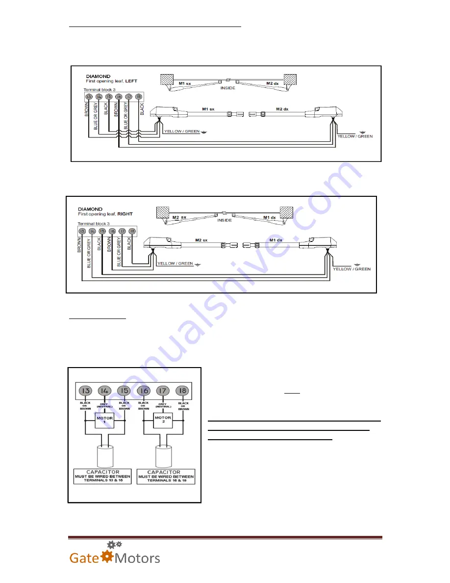
For gates where the LEFT leaf must open FIRST, see below wiring diagram:
For gates where the RIGHT leaf must open FIRST, see below wiring diagram:
Motor Capacitors:
Each motor is supplied with 10uF capacitors. These are designed to help the motor on initial start-up
and continued operation. These capacitors are essential to fit with each motor. If a capacitor is not
fitted, the motor may physically vibrate gently and will fail to operate upon command. The control
board may display a communication fault code (N1 / N2).
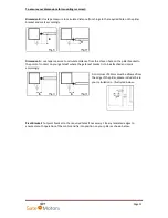
The capacitors are not polarised (negative charge “–“or
positive charge “+”) and
must
be wired across terminals
13 & 15, 16 & 18 - Illustrated left.
Ensure the capacitor connection and the coloured wire
in the terminal it shares with are both touching the
metal contact strip within the terminal.
After many years of operation, capacitors may begin to
leak their charge. Replacement capacitors are available
from GateMotors.

