

15
S-PARK
- rev.1.1_06_2020
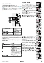
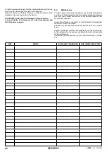
Keys (OPERATION MODE)
Functions
START pulse
START2 pedestrian pulse
together with
(press and while holding press )
Opening command
together with
Closing command
(hold it pressed for short seconds) Programming menu: the
display shows
A.1
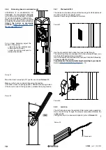
4.1.3
Programming keys
Pressing any key during operation the barrier stops.
With an exception for key : if pressed during countdown the barrier
starts immediately working again, refer to Chapter
e
p. 14.
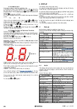
When barrier is in still mode, the display may show “- -” flashing, or
just “- “ if energy save is on and in this circumstance it is possible
to handle the following service keys and functions:
KEY
KEY
KEY
KEY
In programming mode the display alternately shows the outstanding
parameter and its value.
Ex.: parameter
H.2
/ value 1, the display reads first “
H.2
” and after “
01.
”.
In this circumstance it is possible to handle the following programming
keys and functions:
Keys
(PROGRAMMING MODE)
Functions
This key increases the value of the
parameter.
This key decreases the value of
the parameter till 0
This key switches from menu to
menu (ex.
H.3 - J.1
).
From U.x menu the control unit
returns back to
A.1.
This key switches from parameter
to parameter (ex.
H.3 - H.4
).
From last parameter the control
unit returns back to the first one
(ex.
H.6 - H.1
).
together with
This key quits the programming
and returns to operation mode.
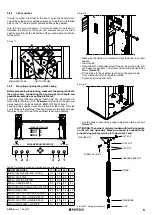
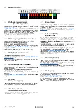
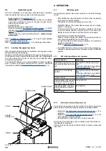
5. PROGRAMMING
5.1
Settings’ configuration
Proceed to programming only when the barrier
is in still mode (any key pressed during operation
stops the barrier).
Press key and hold shortly (a quick pulse is
insufficient): display reads “
A.1
”.
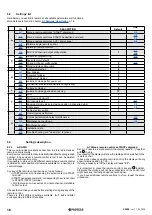
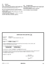
Press
as many times as finding the desired
parameter expressed by an alphabetical letter
(left side of the display).
Then press
as many times as finding the
figure corresponding to the desired parameter
(right side of the display).
Ex.: if you wisht to set parameter
H2
, press
three times (scrolling through
C.1, F.1
and
H.1
), then press again to move to
H.2
.
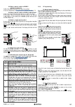
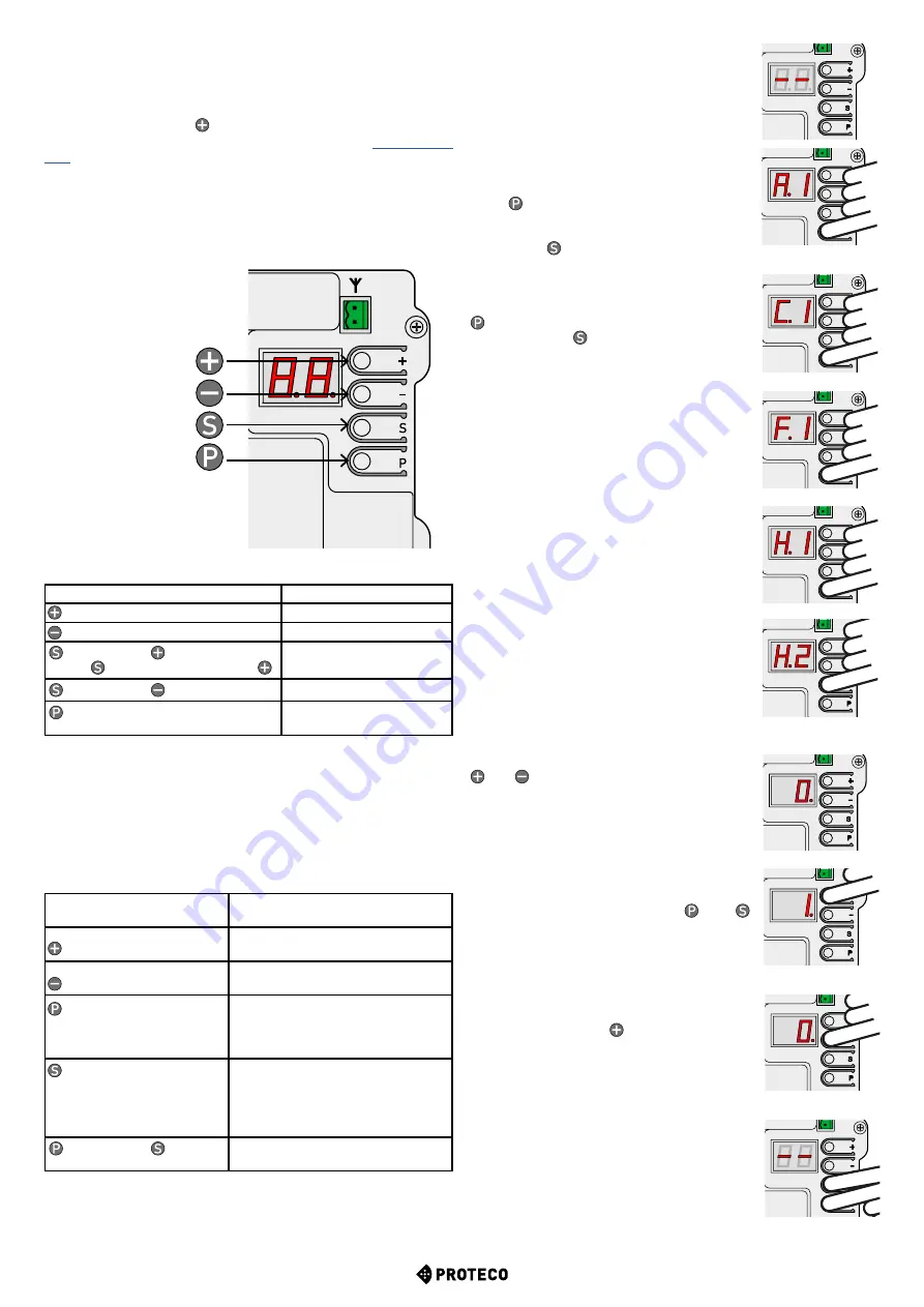
Once the desired parameter is reached, use
and to increase or decrease the value.
Pay attention
: when display reads the desired
parameter, wait a little while to read the
according value.
The screen first reads the parameter and after
its value.
If you wish to move to another parameter,
follow the procedure previously mentioned.
To quit the programming press and
together.
The control unit, however, automatically quits
the programming after two minutes of inactivity.
Some parameters are merely functions and
therefore are not matched to any value.
These functions usually require a longer or
shorter pressure of key
to confirm execution.
Unlike other functions as
A.1, A.2
and
A.3
that do only require a radio signal.
PRESS
P
FOR A LITTLE WHILE
PRESS
P
PRESS
P
PRESS
P
PRESS
S
TO SWITCH
TO NEXT SETTING
DEFAULT
0
PRESS
+
TO INCREASE
PRESS
-
TO DECREASE
PRESS
S - P
TO QUIT
THE PROGRAMMING


