
16
S-PARK
- rev. 1.1_06_2020
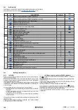
5.2
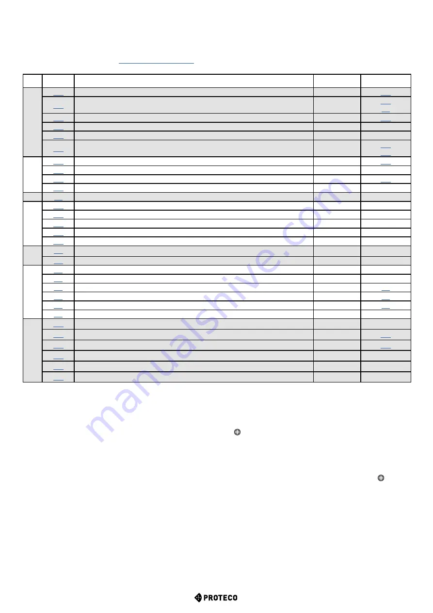
Settings’ list
Here below you will find a resume of all available parameters and functions.
More details are found in Chapter
p. 16.
ID
DESCRIPTION
Default
LINK
A
Store a remote control as “START” command
Store a remote control as START2 pedestrian command
Store a remote control as AUX / 2nd channel
Delete a single remote control
Delete all remote controls
AUX / 2nd channel output configuration
1
C
Automatic programming
Reset (factory default)
Lh and RH boom configuration
2
Working logic configuration
0
F
Obstacle detection
5
H
Pre- blinking
0
Fixed-light blinker
0
“Follow me” closing
0
Automatic closing after power cut
1
TWINNING (master/slave barriers configuration)
0
L
Automatic closing
8
Automatic closing pedestrian opening
12
P
STOP
0
PH (closing photocell)
1
LD (loop detector)
0
Boom light mode when in closing position (optional led strip)
1
Light sensor
0
Cabinet safety switch
1
U
Overall cycles performed
Cycles performed since last maintenance
Maintenance countdown
1
Maintenance recall
0
Installation date
Trouble shooting and “dead man” functions
5.3
Setting’s description
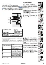
5.3.1
A. RADIO
This menu includes procedures about how to store radio devices,
remote controls mainly.
Every remote control stored is automatically identified by a progressive
number: if by accident a remote control is lost it can be deleted
from the control unit memory.
It is possible to store up to 96 different users; when a remote control
is deleted its radio position still remains available for a new remote
control storage.
Any key of the remote control can be set up as follows:
• START command, corresponding to a wired contact to START
terminal
• START2 pedestrian command, corresponding to a wired contact
to START2 (STRT2) terminal
• AUX feature, known as well as 2nd radio channel, matchable
to AUX output.
Choose the function you need before starting storing any key of the
remote control.
There are three different settings available (
A.1
,
A.2
and
A.3
)
corresponding to different functions.
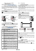
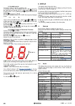
A.1 Store a remote control as START command
Set A.1. Press the remote control (the display reads“
Y-
”) together
with to store.
If successfull the display will show the radio position matched to the
remote control.
In case of an already existing remote control, the display will only
show its radio position (01, 02, …).
If storage capacity is full the display will reads “
FF
”.
It is important to press the remote control’s key and together,
otherwise the storage will not be successfull and the control unit
might save any incoming undesired radio signal.
If you have additional remote controls to store, repeat the same
procedure.


