
17
S-PARK
- rev.1.1_06_2020
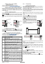
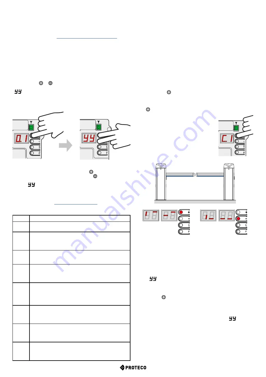
Set
C.1
and press holding during 5 seconds.
If
C.4
is not configurated yet, the display will
show the boom hand (boom has to be in horizontal
position).
Press to set a RH boom or to set a LH boom.
If
C.4
is configurated the display remains clear.
Boom performs 6 steps; every step is shown
on the display (01, 02, 03...) with a short pause
in between.
In any moment it is possible to stop the boom
operation, just pressing any key.
A.2 Store a remote control as START2
pedestrian command
Set
A.2
and repeat the same procedure here above.
For more details refer to
A.3 Store a remote control as AUX/2nd radio channel
Set
A.3
and repeat the same procedure as per
A.1
here above.
At the same time set parameter
A.6
according to the desired
configuration or in alternative use a M
RX-01
optional interface card
module duly set up.
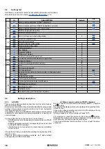
A.4 Delete a single remote control
Every remote control stored is matched to a radio position identified
by a number.
Set A.4, press or
to find the remote control you need to delete
then press both keys together and hold until the display flashes
“
”.
If there is just remote control stored, the display will show just that
one.
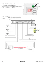
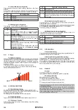
A.6
AUX - Functions/Modes
0
AUX output is OFF.
AUX output is ON if U.4 maintenance recall is activated
1
(default)
2nd channel / MONOSTABLE: the output is activated by a remote
control stored in A.3 AUX. The contact closes when giving
and holding a start pulse with the remote control. The contact
opens just when the remote control’s key is released.
2
2nd channel /BISTABLE: the output is activated by a remote
control stored in A.3 AUX. The contact closes or opens when
giving a start pulse with the remote control.
3
SIGNALLING BOOM IN VERTICAL POSITION: the output is
activated when the boom is in vertical position. If the control unit
came about to be powered it may not detect the boom position,
therefore the signalling light may remain switched off.
4
SIGNALLING BOOM IN HORIZONTAL POSITION: the output is
activated when the boom is in horizontal position.
If the control unit came about to be powered it may not detect
the boom position, therefore the signalling light may remain
switched off.
5
COURTESY LIGHT (30”): the output is activated when the
contact closes and remains closed during the whole working
cycle. The contact opens after 30 seconds after working cycle
is completed.
6
COURTESY LIGHT (60”): the output is activated when the
contact closes and remains closed during the whole working
cycle. The contact opens after 60 seconds after working cycle
is completed.
7
COURTESY LIGHT (90”): the output is activated when the
contact closes and remains closed during the whole working
cycle. The contact opens after 90 seconds after working cycle
is completed.
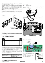
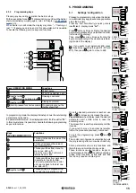
5.3.2
C. Programming
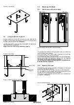
C.1 Boom automatic learning
Boom automatic learning must be perfomed just when installation is
fully completed (balancing included).
The control unit learns about the mechanical features of the boom:
working cycle, speed, torque.
If for any reason mechanical features should change (new accessories
fitted that may affect the boom weight) the automatic learning
procedure shall be repetead.
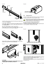
Learning logic: the procedure expects 3-opening steps and 3-closing
steps.
If for any reason one of the steps is cut, procedure shall be repeated
in full.
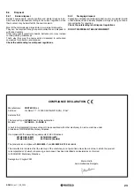
A.5 Delete all remote controls
Set
A.5
, the display will show “
.-
” , press
to confirm you wish
to delete all remote controls stored and hold during 5 seconds;
if all remote controls have been successfully deleted, the display
flashes “
”.
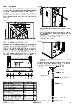
A.6 AUX /2nd radio channel output configuration
The
AUX
is a multifunction output: it can be used as maintenance
recall, refer to chapter (
p. 19).
Or it can set up the following modes/functions:
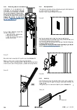
Step (01), boom slowly opens until detecting the mechanical limit
switch.
If the boom works to the opposite direction, stop the operation and
properly set up
C.4
. Then repea
t C.1
.
Step (02), boom slowly lows down until detecting the closing position;
the following steps are meant to set speed, torque and double
check all settings.
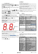
The automatic learning is successfully completed when display
shows “
” flashing.
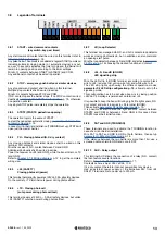
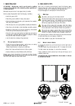
RH BOOM
LH BOOM
C.3 Reset (factory default)
Set
C.3
, press
, hold during 5 seconds to confirm reset (return to
factory settings).
Parameters
U.5, U1
and
U.2 CANNOT
be reset and no remote
control previously stored can be deleted.
Now repeat
C.1 procedure
.
Reset is successfully completed when display shows “
” flashing.


