background image

20

S-PARK

 - rev. 1.1_06_2020


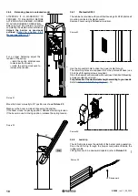
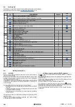
U.5 Installation date

This feature allows to load the installation date. 

The display will show the installation date in 3 different steps: the 

first figure shown is the day (from 1 to 31); pressing 

 the month 

shows up (from 1 to 12); pressing again   the year shows up with 

two dots. 

Pressing   the sequence START. 

EX.: if your installation date is 14-03-2019 the sequence displayed 

will be:


14. 

   03 

   1.9.

If you wish to set installation date, press together   and   holding 

during 4 seconds;  screen will read “d”, use   or    to load the day, 

from 1 to 31; save pressing  . 

Screen will read “n”, use   or   to load the month, from 1 to 12; 

save pressing  .  

Screen wil read “Y”, use   or   to load the year. Save pressing  . 

Installation date loading completed.


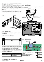
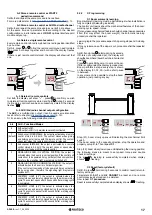
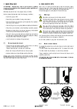
U.6 Trouble shooting and “dead man” functions

Set U.6 and press 

 to confirm.

This feature allows to display the status of all inputs and at the same 

time allows to command direct the boom in “dead man” mode (key 

permanently pressed). 

Press (and hold)   to lift the boom and   to lower it. 

Release the key to stop the boom. 

Attention:

 during all these operations, 

safety  devices  are  not 

working, be carefull.


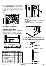
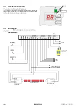
The screen displayes the status of every single input, everyone iden-

tified by a symbol. 

If the input is “active” the according symbol will be lit. 

START, STRT2 (LH symbol), when lit the input is active; Radio dot 

lights up when receiving a radio signal, saved or unknown.  

PH, LD (RH symbol), when lit the input is not active (safety contact 

impeeds the operation). 

CABINET, when lit the cabinet’s door is not closed.  

If one of the 

P.

 settings is OFF (

Chapter 5.3.6 SAFETY

 p. 18), the 

screen will not show any status (symbol permanently switched off).

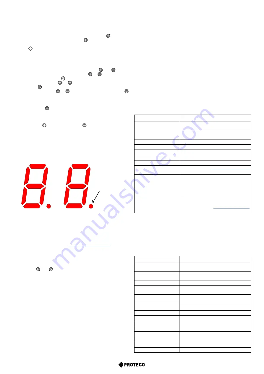
The red dot on the right remains permanently lit to confirm 

programming is ON. 

To quit press   and   together. 
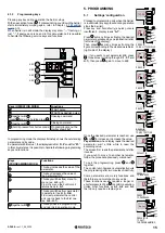
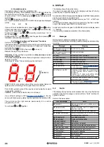
6. DISPLAY

The display shows the barrier status. 

If no key is pressed, after 8 hours the display switches off; shortly 

press any key to light the display up. 

As soon as control unit is powered, the display reads “

8.8.

” (all segments 

are lit so as to detect a possible fault). 

After that the display reads firmware version (ex. “

1.0

”, or “

2.3

” and 

similars). 

If control unit is brand new and no programming has been carried 

out yet, the display reads “

EE

” for a half second.

As last step, control unit goes to STAND-BY mode and display reads 

--

” flashing. 

The remaining messages are listed in the below table.

6.1 Messages

During normal operation messages may show up. 

Refer to the below table indicating possible messages and according 

meaning:

Messages

Meaning

Vertical segments that move 

from center  outwards

The barrier is opening

Vertical segments that move 

from center  inwards 

The barrier is closing

-S

 (start)

Receiving a START command

-P

 (start2 / parziale)

Receiving a START2 command (pedestrian)

-H

 (halt / stop)

Receiving a STOP pulse

CO

 (case open)

Cabinet’s door opened

PC

 (photo close)

Closing photocell is working 

Ld

 (loop detector)

Loop detector LD (

3.8.1.7 LD loop detector


p. 13) is detecting a vehicle

Pair of figures (ex. 02)

Receiving a radio signal by a saved remote 

control (remote control saved on radio 

position 2). 

Usually  S  or  -P    show  up  to  confirm  which 

kind of remote control has been used. 

-C

A timer has been wired to START or START2, 

automatic closing is stopped 

-L

Permanent LD signal (

3.8.1.7 LD loop detector


p. 13) that stops automatic closing 

6.2 Faults

The display shows faults and anomalies that may stop the barrier 

operation: the fault message is coded with two “dots” matched to 

figures or letters. 

Refer to the below table:

DISPLAY message

FAULT

oE

 (encoder)

Obstacle detected due to a sudden slow run 

of the barrier.

oA

 (amperometric)

Obstacle detected due to a sudden motor 

absortion increase

o5

 (standstill)

Obstacle detected due to motor standstill

oC

 (voltage overcharge)

Obstacle detected due to motor voltage 

overcharge (max. limit rate)

Ld

 (loop detector)

Loop detector operating

PC

 (photo close)

Closing photocell operating

AH

 (abort halt/stop)

STOP pulse

AC

 (abort cabinet)

Cabinet’s door is opened

AU

 (abort user)

Operation interrupted using onboard keys 

FC

 (photocell test failed)

Photocell test detected a faulty photocell

EC

 (over current)

Motor absorbs too much current

EY

 (overheating)

Component overheating 

EF

 (start fail)

Barrier fails to start

EU

 (timeout)

Time exceeded

EN

 (encoder wiring)

Motor and/or encoder are not properly wired

START

START2

STOP

RADIO

DOT 

PERMANENTLY 

LIT

CABINET

PH

LD

Summary of Contents for S-Park 4

Page 1: ...1 S PARK rev 1 1_06_2020 S PARK AUTOMATIC ROAD BARRIER User manual ...

Page 2: ... 11 3 7 Wirings 11 3 7 1 Main power 230V 11 3 7 2 Back up batteries 11 3 7 3 Stand alone antenna optional 12 3 7 4 Wiring diagram 12 3 8 Legenda of terminals 13 3 8 1 START wired command contacts key switch key pad timer 13 3 8 2 STOP emergency push button or similar devices 13 3 8 3 STRT2 optional additional START contact 13 3 8 4 PH Closing photocell N C dry contact 13 3 8 5 24 SAFETY Closing ph...

Page 3: ...inker 18 H 3 Follow me closing 18 H 4 Automatic closing after power cut 18 H 6 Master slave barrier configuration 18 5 3 5 L WORKING TIMES 18 L 1 Automatic closing 18 L 2 Automatic closing pedestrian opening 18 5 3 6 P SAFETY 18 P 1 STOP 18 P 2 PH closing photocell 18 P 3 LD loop detector 19 P 4 LED signalling strip optional 19 P 5 Light sensor 19 P 6 Cabinet s safety switch 19 5 3 7 U MAINTENANCE...

Page 4: ...ting from page 21 Proteco S r l reserves the right to make changes to the product without notice Main power Max absorption Motor power Accessories Torque Opening time Operating temperature Duty cycle IP rating 2 TECHNICAL FEATURES 2 1 Main features 230V 50 60 Hz 230V 50 60 Hz 1 2A 230V 1 2A 230V 24V dc 24V dc 24V dc 24V dc 120 Nm 180 Nm 2 5 4 sec 4 5 6 sec 25 C 55 C 25 C 55 C 80 80 max 200 cycles ...

Page 5: ...EN ANTENNA KEY KEY KEY KEY START commands START START2 pedestrian opening STOP Radio 433 MHz embedded radio receiver storage up to 96 random o rolling codes Safety devices Closing photocell loop detector configurable Additional appliances TWINNING mirror barriers timer light sensor Outputs RGB led signalling strip AUX output Optional interfaces Expansion connector for optional modules Connector fo...

Page 6: ...the barrier area has been left While the boom length can be adjusted the concrete basement remains fixed as it is built Picture 2 Boom from 4000 to 6000 mm Picture 2 Overall layout 3 4 Basement preparation It is absolutely key to build a solid concrete basement at least EN206 C25 30 proof Basement dimensions must be no less than 400x500mm and no less than 600mm deep We recommend to consider an ext...

Page 7: ...e barrier hand is determined proceed to fit the spring accordingly as shown in the above picture If you need to change the opening orientation complete the installation first and then follow the instructions rotating to 90 the equalizer lever before repositioning the boom and spring ATTENTION FOR SAFETY REASONS REMOVE THE BOOM JUST WHEN IN VERTICAL POSITION 3 6 2 Mounting of the boom After determi...

Page 8: ...ARTMENT AS SHOWN IN PICTURE 14 Picture 14 3 6 3 Manual operation In order to facilitate adjustments balancing spring and limit switch regulation put the barrier in manual operation mode Put the barrier to manual operation mode just after completing the whole installation Be carefull when releasing the boom it could accidentally lift up and be dangerous Use the lock located on the right side of the...

Page 9: ...nd put the boom to vertical position Lock it again Drive the M12 hexagonal screw through the spring hole and put a washer as spacer The screw s head must be oriented as shows Picture 18 Fit the spring to the equalizer lever using the proper hole Put a washer in order to facilitate rotation Tighten bolt and washer M12 Use the hook to secure the spring to barrier s plate as shows Picture 19 ATTENTIO...

Page 10: ... of the barrier during operation Drive the LED strip through the proper compartment inside the rubber profile LED lights have to be downward oriented refer to Picture 25 Picture 25 LED downward Picture 21 For a proper balancing adjust the tension of the spring rotate the spring anticlockwise to decrease the tension rotate the spring clockwise to increase the tension Move the boom manually to 30 po...

Page 11: ...led on the same drive way as shows the above picture can work simultaneously if wired together on TWIN terminals The master barrier will command the slave barrier slave barrier may only stop if detecting an obstacle during operation Any safety and command devices shall be wired to the master barrier only As well the master barrier is the only one that shall perform pede strian opening terminal STA...

Page 12: ...al stand alone atenna remove the Whip aerial and wire the core cable RG58 wire the shield cable on the other terminal as shown in the picture SHIELD CORE 3 7 4 Wiring diagram The below diagram is a mere overall view about all possible wirings AUX TWIN SLAVE BARRIER LED STRIP LOOP DETECTOR NO or NC contact TRANSMITTER RECEIVER INFRARED BEAM ...

Page 13: ...g photocell test 3 8 6 TX Closing photocell cuts power during photocell test This terminal powers at 24Vdc 0 3A all safety devices but unlike 24 SAFETY cuts the power during photocell test 3 8 7 LD Loop Detector This terminal can manage both N O and N C contacts loop detector works as closing photocells do but in addition can also command an opening start pulse Wire the loop detector between LD an...

Page 14: ...he display is in stand by _ _ OPENING MODE The blinker flashes slowly and the display shows opening If during opening the barrier detects an obstacle the boom reverts to closing position remains still for 10 seconds the display shows count down and then starts to open again AUTOMATIC CLOSING COUNTDOWN When countdown begins the blinker starts flashing briefly for a few seconds switiching then to fi...

Page 15: ...y quits the programming and returns to operation mode 5 PROGRAMMING 5 1 Settings configuration Proceed to programming only when the barrier is in still mode any key pressed during operation stops the barrier Press key and hold shortly a quick pulse is insufficient display reads A 1 Press as many times as finding the desired parameter expressed by an alphabetical letter left side of the display The...

Page 16: ...ption 5 3 1 A RADIO This menu includes procedures about how to store radio devices remote controls mainly Every remote control stored is automatically identified by a progressive number if by accident a remote control is lost it can be deleted from the control unit memory It is possible to store up to 96 different users when a remote control is deleted its radio position still remains available fo...

Page 17: ...sition therefore the signalling light may remain switched off 5 COURTESY LIGHT 30 the output is activated when the contact closes and remains closed during the whole working cycle The contact opens after 30 seconds after working cycle is completed 6 COURTESY LIGHT 60 the output is activated when the contact closes and remains closed during the whole working cycle The contact opens after 60 seconds...

Page 18: ...INNING OFF 1 Set 1 to configurate the master barrier 2 Set 2 to configurate the slave barrier 5 3 5 L Working times L 1 Automatic closing This parameter sets the automatic closing time adjustable from 0 automatic closing OFF to 99 seconds L 2 Automatic closing pedestrian opening This parameter sets the automatic closing time for pedestrian opening adjustable from 0 automatic closing OFF to 99 seco...

Page 19: ...mmediately stops working just figure out if accidentally a radio start command is given how dangerous it could be However barrier can be managed in dead man mode using on board keys P 6 safety function may be switched OFF setting P 6 to 0 position by default P 6 is ON P 6 1 U 3 Maintenance countdown This feature allows to set the number of cycles till next maintenance service starting from a minim...

Page 20: ...version ex 1 0 or 2 3 and similars If control unit is brand new and no programming has been carried out yet the display reads EE for a half second As last step control unit goes to STAND BY mode and display reads flashing The remaining messages are listed in the below table 6 1 Messages During normal operation messages may show up Refer to the below table indicating possible messages and according...

Page 21: ...8 END USER S TIPS Dear user it is highly recommended to read the following pages because they may contain essential information for the safety of people and things and in compliance with applicable laws Store these pages in a safe place for future reference 8 1 Warnings Keep the system away from children under 8 Children and People with reduced physical sensory mental or limited experience and or ...

Page 22: ... 8 3 Maintenance In order to preserve the proper performance and safety of the barrier over time it is highly recommended to schedule a regular maintenance plan with your installer and report any uncommon behaviors that may require inspection In case of malfunctions it is wise to contact the installer who installed the barrier rather than others End user may just keep clean photocells and the barr...

Page 23: ...arrier automation Models S PARK 4 S PARK 6 Is built to be integrated into a machine or to be assembled with other machinery to crate a machine under provisions of 2006 42 EC Machinery Directive It complies with the essential requirements of EEC Directives 2014 30 UE EMC 2014 35 UE LVD 2014 53 UE RED 2011 65 CE RoHS2 The product also complies with EN 60335 1 and EN 60335 2 103 standards The manufac...

Page 24: ...24 S PARK rev 1 1_06_2020 Proteco S r l Via Neive 77 12050 CASTAGNITO CN ITALY Tel 39 0173 210111 Fax 39 0173 210199 info proteco net www proteco net ...

Reviews: