
4
S-PARK
- rev. 1.1_06_2020
1. WARNING
This manual for S-Park series contains important information concerning personal safety.
An incorrect installation or an improper use may lead to severe injuries.
Read carefully and pay particular attention to the safety sections marked by the yellow triangle.
S-PARK series is projected to control transit areas; if necessary, provide a special and separate entry way for pedestrians.
The installation of automatic doors, gates and barriers must comply with the Machinery Directive 2006/42/CE and EN 12453
regulation, and performed by qualified personnel.
Make sure the main power line is equipped with state of the art safety grounding system; as well be sure the whole installation is
protected by a power cut switch and against overcurrent.
Make sure the area is clear from flammable gases and/or electromagnetic interferences: it could lead to very dangerous injuries.
Switch the power and batteries OFF before any operation.
After installation, packaging and waste materials (cardboard, plastic, metal parts etc.) must be kept away from children as they could be
potentially harmfull.
Use only original spare parts. Any alteration to the system is prohibited. Proteco Srl will not respond in case of using additional and/or
fake spares.
Before commissioning the system, deliver the last pages of this manual to the user (section 8. END USER’S TIPS starting from
page 21).
Proteco S.r.l. reserves the right to make changes to the product without notice.
Main power
Max. absorption
Motor power
Accessories
Torque
Opening time
Operating temperature
Duty cycle
IP rating
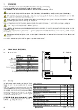
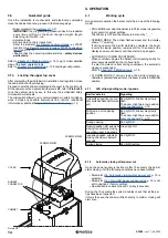
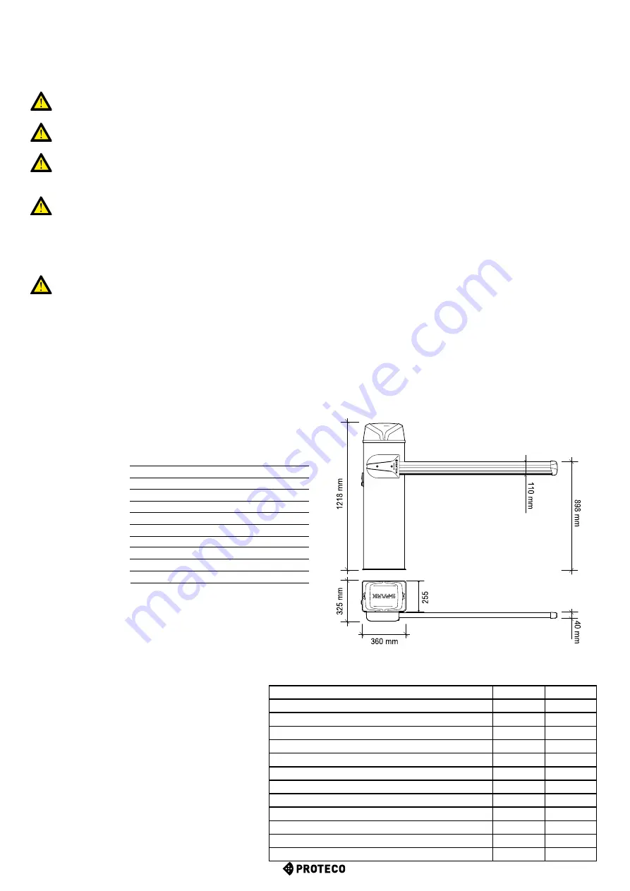
2.
TECHNICAL FEATURES
2.1
Main features
230V 50/60 Hz
230V 50/60 Hz
1,2A @ 230V
1,2A @ 230V
24V dc
24V dc
24V dc
24V dc
120 Nm
180 Nm
2.5 ÷ 4 sec.
4.5 ÷ 6 sec.
-25°C ÷ +55°C
-25°C ÷ +55°C
80% 80%
(max 200 cycles/hour) (max 130 cycles/hour)
54 54
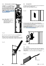
S-PARK 4 S-PARK 6
Boom up to 4 m Boom from 4 to 6 m
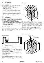
Fig. 1: Dimensions
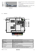
2.2
Life line
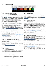
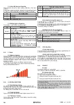
The life of the barrier may be affected by multiple waste factors.
The life expectation can be calculated using the following
criteria.
In order to get the barrier waste rate refer to the information
included in
Table 1
, add together all values that comply with
the installation scenario along with the accessories installed.
The result achieved will be a value between 0 and 10, and it
represents the waste rate to be applied on the below graph
to calculate the estimated life rate.
ATTENTION: If the waste rate obtained is beyond
10, move to a superior barrier version in order to
fulfill the expected performances .
S-Park 4
S-Park 6
Boom from 3 to 4 m length
1
-
Boom from 5 to 6 m length
-
2
Photocell operation frequently cut
1
1
Normal operation frequently cut due to obstacle
0,5
1
Seaside areas
0,5
0,5
Sandy and dusty areas
1
1
Significantly windy areas
1
2
Articulated boom
2
2
Boom fitted with moving support
1
2
Boom fitted with hanging rack
1
1,5
Boom fitted with led strip
0,5
1
Outside temperatures often beyond 40° or below 0°
0,5
0,5
Table 1: Waste rate


