

6
S-PARK
- rev. 1.1_06_2020
500 mm
500 mm
600 mm
500 mm
400 mm
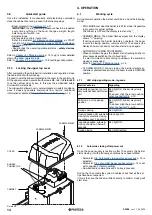
3. INSTALLATION
3.1
Introduction
For a proper installation, strictly follow the following procedure, re-
specting the below chronological order:
• Prepare a strong basement using ferro concrete.
• Fix the cabinet to ground.
• Fit the boom and accessories.
• Adjust and balance the spring.
• Proceed to self-learning programming and adjust settings.
Additional information:
• TWINNING function, it allows to manage two mirror barriers.
• RGB led singnalling strip available to complete the boom.
• Photocells and similar safety obstacle detection devices can be fitted.
3.2
Preliminary checks
Before proceeding to installation, it is necessary to double check
the good condition of every component of the barrier and make
sure the site is suitable for installation purposes.
• All components must be integral and suitable to use.
• Make sure the installation site complies with system’s dimensions.
• Make sure the concrete basement grants stability and solidity.
• Make sure the area around the barrier is clear enough to allow
eazy and safe manual operation.
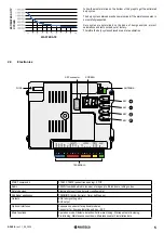
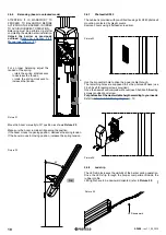
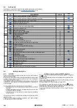
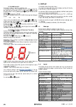
3.3
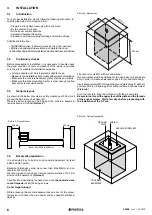
General layout
As shown in the below plan view, a safety clearance of 500 mm all
around the barrier area has been left.
While the boom length can be adjusted, the concrete basement
remains fixed as it is built
(Picture 2)
.
Boom from 4000 to 6000 mm
Picture 2: Overall layout
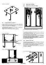
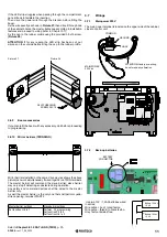
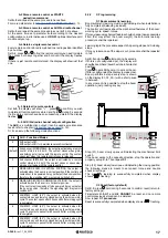
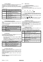
3.4
Basement preparation
It is absolutely key to build a solid concrete basement (at least
EN206 C25/30 proof).
Basement dimensions must be no less than 400x500mm and no
less than 600mm deep.
We recommend to consider an extra concrete surface of 200 mm
all around the basement.
(Picture 3)
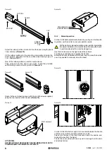
Pay attention while arising the basement, since
the concrete work
cannot impede
to stud the fixing screws.
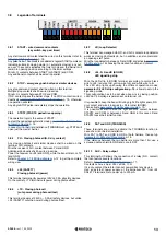
Do not forget wirings!
While preparing the concrete basement keep a duct of the proper
dimension to connect the main power and any possible additional
devices.
Picture 3: dimensions
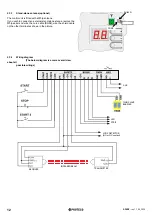
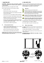
Fit anchor screws M10 with nut and washer.
Nut and washer must be positioned in the same way for each single
bolt, in order to create a balanced support for ground plate fixing.
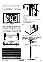
Insert anchor screws M10 through the ground plate holes, fit washers
and nuts M10 to protruding part of anchor screws, as shown below.
(Picture 5)
Pour the concrete, flush the surface and fix the ground plate.
Be careful not to soil the upper face of the plate and the threads
of the anchor screws. Wait a few days before proceeding with
the installation of the S-Park.
Picture 4: Cabinet foundation
CONCRETE
BASEMENT
GROUND
PLATE
ANCHOR SCREW M10
WIRING


