
18
S-PARK
- rev. 1.1_06_2020
C.5 Working logic configuration
It is possible to set 3 different working logics:
C.5
Working logic
0
(default)
SEQUENTIAL
Every START command stops or reverts the working
cycle according to the sequence:
OPEN – STOP –
CLOSE – OPEN ...
1
PRIORITY TO OPENING
Every START command gives priority to opening; boom
automatically closes according to the time set (refer to
L.1 Automatic closing
)
2
STEP BY STEP
START terminal commands the opening; START2 terminal
commands the closing.
Automatic closing activates if configurated, refer to
L.1
Automatic closing
and
L.2 Automatic closing
pedestrian opening
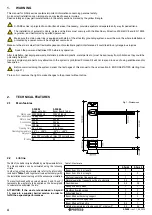
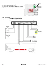
5.3.3
F. Torque
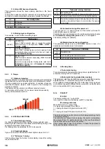
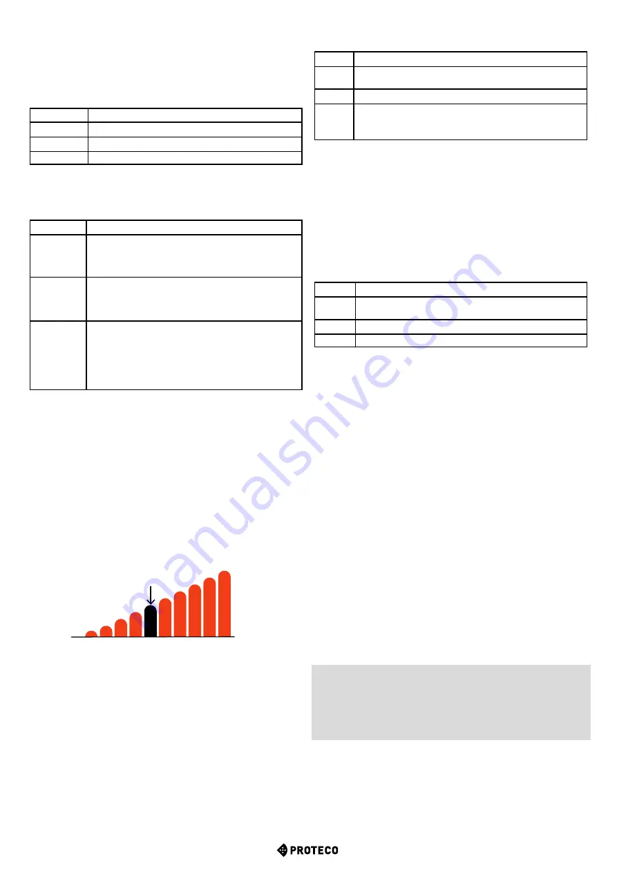
F.1 Obstacle detection
Obstacle detection is a safety feature that complies with outstanding
regulations and makes the barrier area more protected and safer.
If during operation any speed alteration or sudden stress are
detected, the barrier stops in order to avoid or limit damages to
persons or objects.
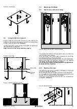
This feature can be adjusted on different sensitivity levels:
0 = detection is OFF while 10 = maximum detection sensitivity;
factory value (default) is set to 5.
H.3
“Follow me” closing - Functions
0
(default)
The function is OFF.
The barrier closes according to the automatic closing time set up.
1
The barrier closes 2 seconds after completing the opening.
2 ... 10 The barrier closes according to the delay time set, from 2 to 10
seconds when photocell beam is cut and before the opening
is completed.
H.4 Automatic closing after power cut
If you set H.4 to 1, in case of power cut the barrier will close 15
seconds after power is restored.
This function can be activated only if conditions included in chapter
4.1.2 Automatic closing after power cut
, p. 14 are applied.
The factory setting is 1 (default).
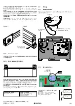
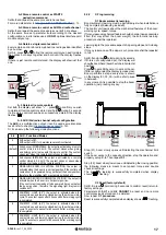
H.6 Master/slave barrier configuration
This parameter allows to set up TWINNING feature in case of a
double barrier installation (mirror barriers).
H.6
Master/slave (TWINNING)
0
(default)
TWINNING OFF
1
Set 1 to configurate the master barrier
2
Set 2 to configurate the slave barrier
5.3.5
L. Working times
L.1 Automatic closing
This parameter sets the automatic closing time, adjustable from 0 =
automatic closing OFF to 99 seconds.
L.2 Automatic closing (pedestrian opening)
This parameter sets the automatic closing time for pedestrian opening,
adjustable from 0 = automatic closing OFF to 99 seconds.
L.1
and
L.2
are totally independent one to the other: they can be set
up in different ways with different times, as well
L.1
can be ON while
L.2
can be switched OFF, and viceversa.
5.3.6
P. SAFETY
P.1 STOP
The factory setting is 0 = output OFF.
If you wish to connect a stop device, set
P.1
to 1position.
P.2 (closing photocell)
When
P.2
is set to 0 = output OFF
It is highly recommended to set
P.2
to:
1 = closing photocell ON (photocell test is OFF)
or
2 = closing photocell ON (photocell test is ON)
The photocell test is a safety provision that helps detecting a faulty
or unsafety photocell.
The test works as follows: before closing, the control unit switches
the power off from TX photocell terminal, in this way the photocell
has no other option but to open the contact.
If the contact doesn’t open in short time, it means the photocell is
faulty and the barrier remains still.
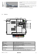
5.3.4
H. SPECIAL FUNCTIONS
H.1 Pre-blinking in closing
Pre-blinking feature warns the user that closing will start soon.
Receiving a start command the blinker starts flashing during a few
seconds before boom starts closing.
Pre-blinking time is adjustable, from 0 to 8 seconds.
H.2 Fixed-light blinker
If you wish to switch the blinker to fixed-light mode, set H.2 to 1.
H.3 “Follow me” closing
This function allows the barrier to immediately close after cutting
the photocell beam.
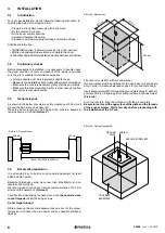
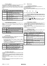
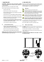
C.4
Boom configuration
0
RH barrier
1
LH barrier
2 (default)
No configuration is set
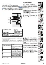
C.4 LH and RH boom configuration
This parameter shows the boom opening direction or the boom
position.
Looking from inside the property (cabinet’s door inside the property)
and boom in horizontal position, values are intended as follows:
MIN. 0
1 2 3 4
5
6 7 8 9
10 MAX.
DEFAULT


